Introduction
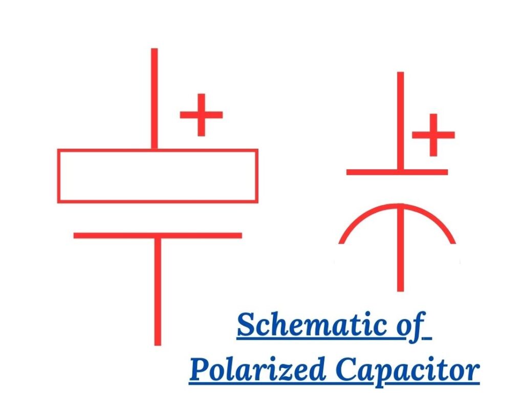
In this article, we will be focusing on electrolytic capacitors and their various types and symbols. An electrolytic capacitor is a type of capacitor that uses an electrolyte as one of its plates to achieve a larger capacitance. It is commonly used in electronic circuits for its ability to store and release electrical energy. One important thing to note about electrolytic capacitors is their polarity. They have a positive side and a negative side, and it is crucial to connect them correctly in a circuit. Electrolytic capacitors play an important role in PCBs. The schematic symbol for an electrolytic capacitor consists of two parallel lines with a curved line at one end. The curved line represents the positive side of the capacitor, while the straight lines indicate the negative side. It is essential to pay attention to this symbol when designing or reading circuit diagrams. There are different types of electrolytic capacitors, each with its own unique symbol and construction.
The SMT Can Style electrolytic capacitor is a surface-mount component that is widely used in modern electronics. It has a cylindrical shape and is soldered directly onto the surface of a circuit board. Another surface-mount option is the SMT Case Electrolytic capacitor. It has a rectangular shape and is also soldered onto the surface of a circuit board. Both these types of capacitors have clear markings indicating the positive and negative sides. For through-hole mounting, we have the PTH Radial electrolytic capacitor and the PTH Axial electrolytic capacitor. The PTH Radial capacitor has two leads that are inserted through holes in the circuit board and soldered on the other side. The PTH Axial capacitor, on the other hand, has one lead that is inserted through a hole and the other lead that is soldered on the surface of the board. So, what exactly is an electrolytic capacitor? Let's explore!
The Electrolytic Capacitor
An electrolytic capacitor is a type of capacitor that is commonly used in electronic circuits. It is designed to store and release electrical energy, and it is particularly suited for applications that require high capacitance values. Electrolytic capacitors are made up of two conductive plates, known as electrodes, that are separated by an electrolyte. The electrolyte is a conductive solution or gel that allows the flow of electric current between the plates. One of the electrodes is made of aluminum, while the other is typically made of a conductive material such as graphite or carbon.
Electrolytic capacitors have the ability to store a large amount of charge in a small package. This is due to the use of a thin dielectric layer, which is formed by an oxide layer on the surface of the aluminum electrode. The dielectric layer acts as an insulator, preventing the flow of current between the plates. Electrolytic capacitors are polarized, which means that they have a positive and a negative terminal. It is important to connect them correctly in a circuit, as reversing the polarity can cause the capacitor to fail or even explode. The positive terminal is usually marked with a plus sign or a stripe, while the negative terminal is marked with a minus sign or a longer lead. These capacitors are commonly used in power supply circuits, audio amplifiers, and other applications that require high capacitance values. They are known for their reliability, long lifespan, and ability to handle high voltages.
Schematic Symbol
Understanding the schematic symbol for an electrolytic capacitor is an important step in reading and interpreting electronic circuit diagrams. By recognizing and correctly connecting the capacitor, you can ensure the proper functioning of your electronic circuits and avoid any potential damage or malfunctions. So, what does the schematic symbol for an electrolytic capacitor look like? In electronic circuit diagrams, the electrolytic capacitor is represented by a unique symbol that facilitates easy identification. The schematic symbol consists of two parallel lines with a curved line connecting them. One of the parallel lines has a small plus (+) sign, indicating the positive terminal, while the other line has a small minus (-) sign, representing the negative terminal. It is crucial to note that the polarity of the electrolytic capacitor is significant. Incorrect connections can result in damage or failure of the capacitor and potentially affect other components in the circuit.
SMT Can Style Electrolytic Capacitor
The SMT Can Style Electrolytic Capacitor is designed to be mounted directly on the surface of a printed circuit board (PCB), eliminating the need for additional space. This compact design allows for more efficient use of space within electronic devices. The high capacitance values make them suitable for applications that require large amounts of charge storage. The SMT Can Style Electrolytic Capacitor has a low ESR, which means it has minimal resistance to the flow of alternating current (AC). This low resistance allows for efficient energy transfer and helps to reduce power losses in electronic circuits. These capacitors are designed to have a long lifespan, with some models rated for thousands of hours of operation. This durability makes them suitable for use in applications that require reliable and long-lasting performance. SMT Can Style Electrolytic Capacitors are designed to operate over a wide temperature range, making them suitable for use in both high and low-temperature environments.
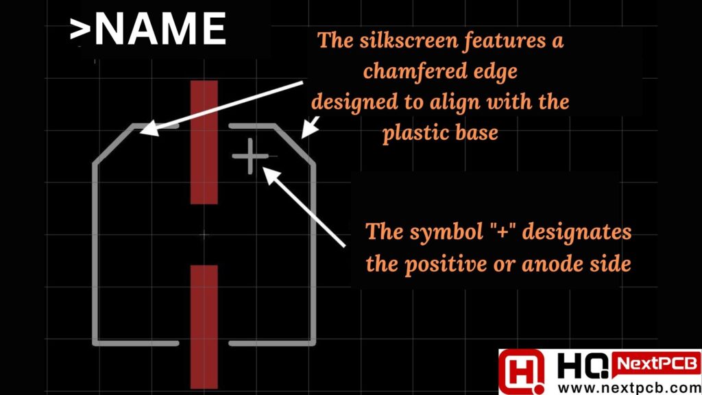
Electrolytic capacitors in SMT (Surface Mount Technology) style feature a distinctive black mark on the top of the can. While the color of this mark may vary depending on the manufacturer, the positive or anode side of the capacitor is consistently chamfered on the plastic base. In the case of SMT Can Electrolytic Capacitors, the marking serves to identify the negative or cathode side.
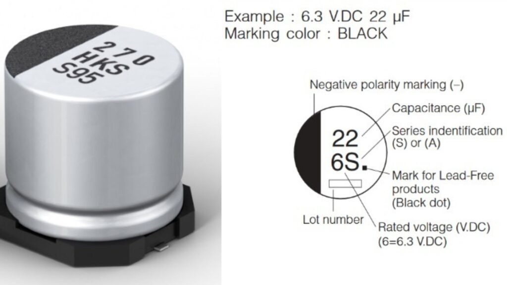
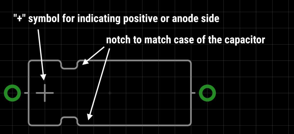
The footprint of a standard SMT can electrolytic capacitor is represented by the SMT EL Footprint, providing a visual reference for its layout and configuration.
SMT Case Electrolytic Capacitor
SMT case electrolytic capacitors are compact and efficient capacitors designed for surface mount applications. They are commonly used in electronic devices such as smartphones, laptops, and televisions. These capacitors are known for their high capacitance values and low Equivalent Series Resistance (ESR), making them ideal for applications that require high energy storage and low power losses. SMT case electrolytic capacitors are smaller in size compared to other types of capacitors, allowing for more efficient use of space on circuit boards. These capacitors offer high capacitance values, allowing for the storage of large amounts of energy.
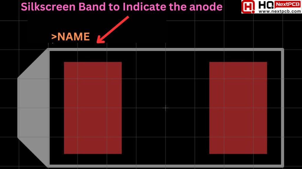
SMT case electrolytic capacitors have low ESR, resulting in minimal power losses and improved overall efficiency. They can operate reliably in a wide temperature range, making them suitable for various environmental conditions. SMT Case Electrolytic Capacitors are a type of capacitor shaped like an 0805 resistor or ceramic capacitor. They usually contain materials like tantalum or niobium. Unlike other capacitor packages, these ones are typically marked on the positive side. Just pay attention to the positive marking when dealing with them. The marking is shown in the SMT casemarking.
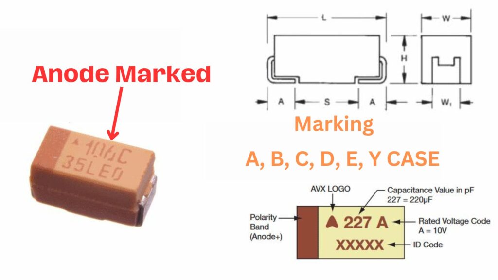
SMT Case Marking The layout and configuration of these capacitors can be understood through the visual guide provided by the SMT case footprint.
PTH Radial Electrolytic Capacitor
The PTH radial electrolytic capacitor is known for its high capacitance and low Equivalent Series Resistance (ESR), making it ideal for applications that require stable and reliable performance. It is commonly used in power supplies, audio amplifiers, motor control circuits, and many other electronic devices. One of the key advantages of the PTH radial electrolytic capacitor is its compact size, which allows it to be easily integrated into circuit boards. This makes it a popular choice for manufacturers who need to optimize space in their designs.
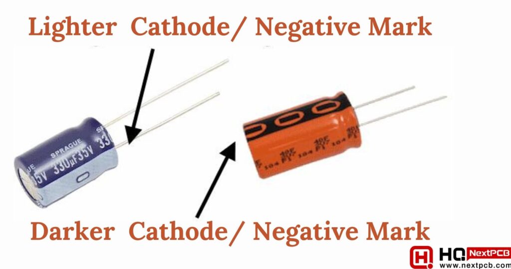
Furthermore, the PTH radial electrolytic capacitor is designed to withstand high temperatures and voltage levels, ensuring its durability and longevity. This makes it suitable for use in demanding environments where other capacitors may fail. PTH Radial Electrolytic Capacitors are a specific type where both the anode and cathode come out from one side of the capacitor. Most of the time, these capacitors have a noticeable contrasting strap along the cathode or negative side. The markings, as shown in the PTH Radial Markings, help identify the polarization of these capacitors.
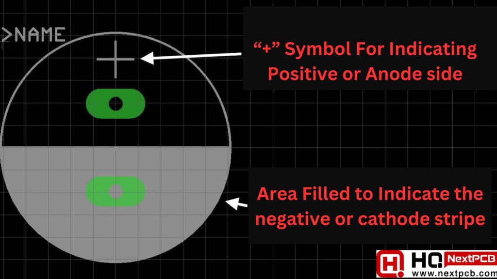
For understanding the layout and configuration, you can refer to the PTH Radial Footprint, which provides a visual guide for PTH radial-style electrolytic capacitors.
PTH Axial Electrolytic Capacitor
PTH Axial Electrolytic Capacitors, while not as commonly used, have an interesting marking feature. Similar to radial style capacitors, they have a negative or cathode band running down the side. However, what sets the PTH Axial Electrolytic Capacitor apart from other capacitors is its construction. With its axial lead design, this capacitor is easy to install and solder onto a printed circuit board. Its compact size makes it ideal for space-constrained applications, ensuring that your circuit board remains neat and organized.
But it's not just the physical design that makes the PTH Axial Electrolytic Capacitor a standout. Its electrolytic construction allows for high capacitance values, making it perfect for applications that require large amounts of charge storage. Whether you're working on audio equipment, power supplies, or industrial control systems, this capacitor can handle the job. Another advantage of the PTH Axial Electrolytic Capacitor is its long lifespan. With its high-quality materials and superior manufacturing processes, this capacitor is built to last. You can trust that it will continue to perform reliably even in demanding environments.
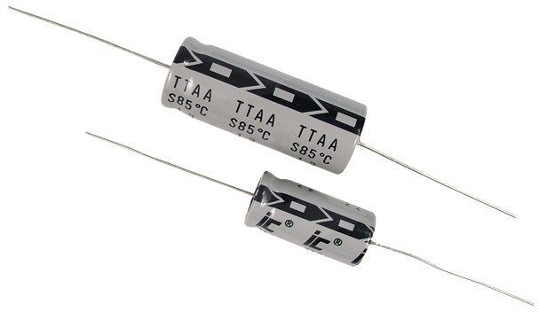
In the illustration labeled "Iccaps 1," you can see the cathode strip pointing towards the cathode. This arrow is a key indicator for proper orientation.
For understanding the layout and configuration of PTH Axial Electrolytic Capacitors, you can refer to the provided visual guide in the PTH Axial Cap illustration.
Components Free Worldwide Shipping
Conclusion
In conclusion, electrolytic capacitors are an essential component in electronic circuits. They are widely used due to their high capacitance values and ability to store and release electrical energy efficiently. In our previous article, we already discussed electrolytic capacitor precautions and difference between SMT and SMD. We have discussed the different types of electrolytic capacitors, including the SMTCanStyle, SMTCase, PTHRadial, and PTHAxial capacitors. Each type has its own unique characteristics and applications. Furthermore, we explored the schematic symbols used to represent electrolytic capacitors in circuit diagrams. It is important to understand these symbols to correctly identify and use capacitors in electronic circuits. Additionally, we touched upon the polarity of electrolytic capacitors. It is important to correctly identify the positive and negative sides of the capacitor to avoid damaging the circuit or the capacitor itself. Overall, electrolytic capacitors play an important role in electronic circuits, providing energy storage and filtering capabilities. Understanding their different types, schematic symbols, and polarity is essential for successful circuit design and troubleshooting. Stay tuned for more articles in The Footprint Files series, where we delve deeper into electronic components and their applications.
Comment