Hello everyone, I hope you all are doing great. In today’s tutorial, we are going to design an IoT-based Heart Rate Monitoring System with ESP32 Microcontroller Board. Remote Health Monitoring Systems are evolving in the modern tech world because of their immense advantages, especially in rural areas where healthcare facilities are not readily available. Nowadays, these remote healthcare systems are even embedded in wearable devices to promptly warn doctors about their patient's health conditions.
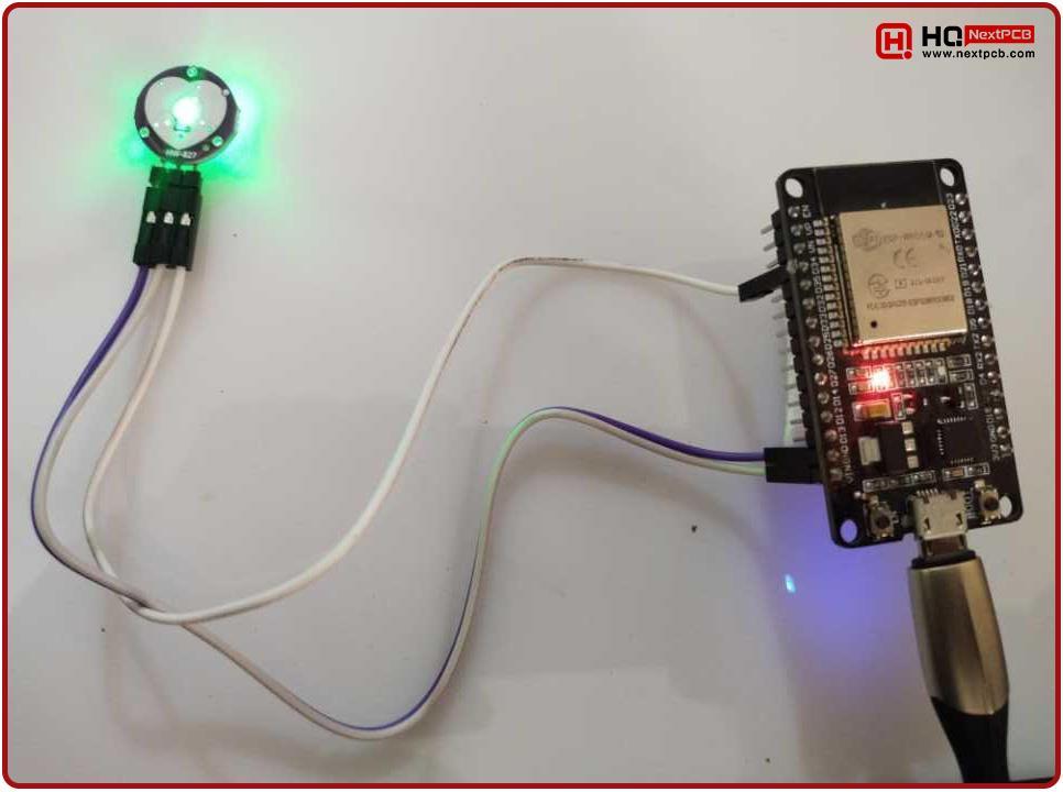
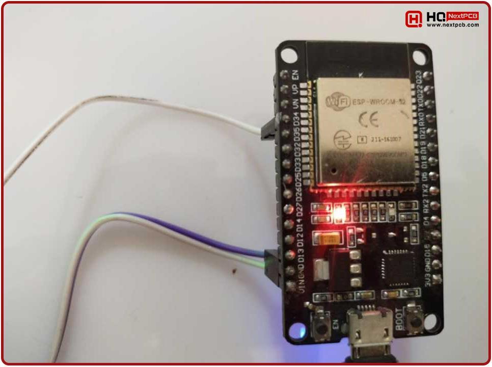
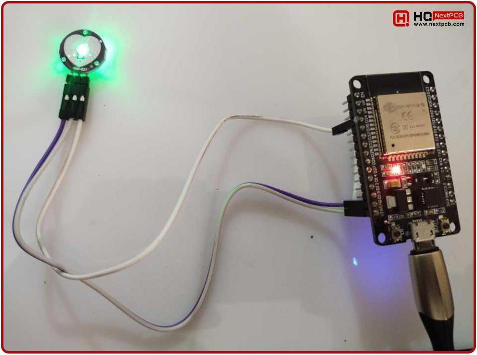
In today’s project, we will use a Pulse Sensor to monitor the Patient’s Heart Rate and will send its data over the WebServer, so that a doctor can easily analyze it from anywhere in the world. In order to remotely monitor the heart rate data, we will plot a heart rate graph for visual demonstration. Here’s the hardware setup of our project:
So, let’s first have a detailed understanding of the Pulse Sensor, we are using today:
SEN-11574 Pulse Sensor
We are using the SEN-11574 Pulse Rate Sensor to monitor the Heartbeat of the patient. The SEN-11574 is a pulse sensor that detects the heartbeat rate. It is a small, low-cost, plug-and-play heart rate sensor that works with Arduino and almost all Arduino-compatible boards. We know that it is usually challenging to measure the exact heartbeat rate, but by using this sensor, this task can be greatly simplified. In this regard, the heartbeat is defined as:
“The heartbeat is a periodic signal generated by a software or hardware system to indicate the normal functioning of any system.”
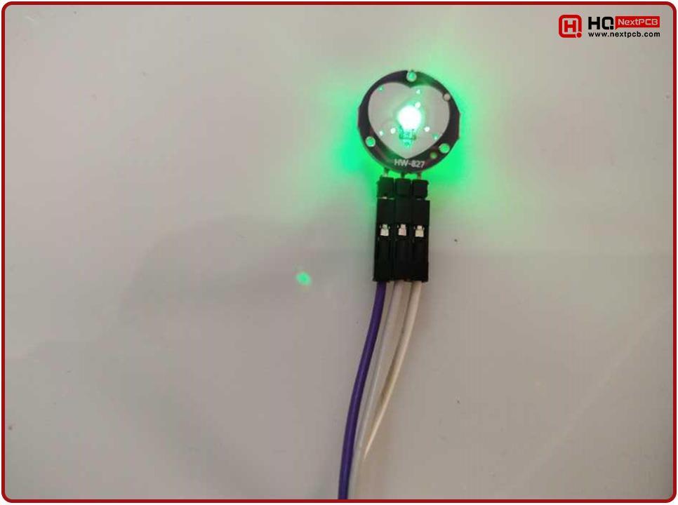
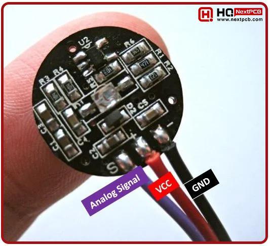
Various sensors are used to measure the periodic intimation signals, but we will highlight the SEN-1157 pulse sensor amped. This small sensor is easily available on the market and is used by students, artists, athletes, makers, and game & mobile developers because of its easy incorporation into circuits. Below is the image of this sensor:
There are various examples of its applications in the circuits that we use in our daily lives:
- Medical monitoring devices
- Fitness trackers
- Heart rate monitors
- Sleep tracking devices
- Stress detection systems
- exercise machines
Components Free Worldwide Shipping
Pulse Sensor Internal Circuitry
The basic components present in its internal structure are:
- Optical heartbeat sensor
- Amplification circuit
- Noise cancellation circuit
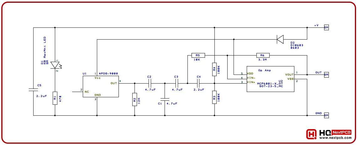
Along with these, the passive components are present, and the figure given below will show you its internal structure:
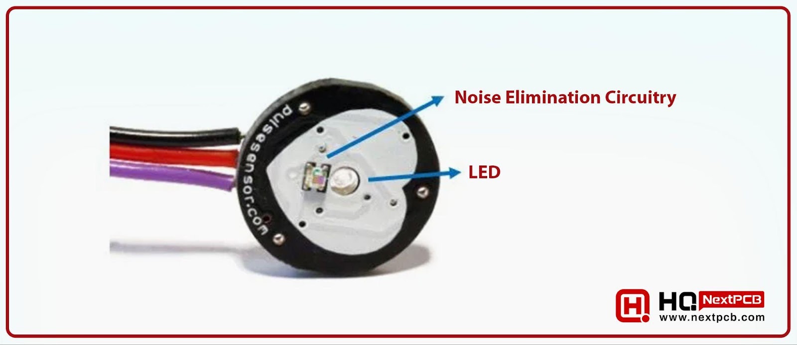
On the front side of this sensor, an LED is present, and there is a hole where the user can see the glow of Kingbright’s reverse-installed green LED. A photodetector LED and noise elimination circuitry are also present under the LED. The basic purpose of eliminating circuitry is to enhance the reading of the heart rate pulse sensor to improve its performance.
Pulse Rate Sensor Pinout
There are three pins present in this sensor, and the description of each of them is given here:
- In the first place, the ground pin is present, which is connected to the ground terminal of the circuit.
- The middle pin is called the Vcc pin, and it is used to provide the power supply to the sensor. This pin works on 3.3V to 5V DC voltages.
- The third pin is the analog pin and is labeled as A0. It receives the analog signal from the circuit and converts it into electrical signals.
There is a need to measure the voltage waveform to extract the heartbeat rate. Here, the central LED, noise-eliminating circuitry, and amplification circuit help to get the output. To simplify it, the pin configuration of this circuit is shown in the table shown here:

|
|
|
|
|
|
|
|
|
|
|
|
The figure of these pins is presented below:
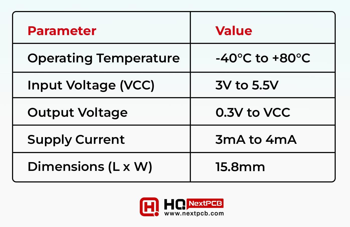
Pulse Rate Sensor Specifications
Before moving forward, let’s have a look at the specification table of this sensor:
|
|
|
|
|
|
|
|
|
|
|
|
|
|
|
|
|
|
Pulse Rate Sensor Working Principle
Recall that the heartbeat rate is the ratio between two consecutive heartbeats, and the circulation of the blood in the human body squeezes the capillary tissues. The volume of the capillary tissues increases and decreases consecutively, and this change in volume affects the heart rate pulse sensor’s LED. After every heartbeat, the LED transmits the light, which is then measured by the controller connected to the sensor. Although the volume change is very light, the high sensitivity of the detector can sense it. This is the reason we say that the LED helps in the sensing of the pulse sensor.
The above discussion was about how the internal circuit works to detect the heartbeat, but the procedure to detect the heartbeat rate is elaborated on in the points given below:
Light Emission
The sensor emits the light, and when the user places their finger on the front side of this heartbeat sensor, the reflection of the LED light changes.
Light Detection
The photodetector sensor senses the amount of light changed (absorbed or reflected) by the blood vessel which is proportional to the change in the blood volume of the capillary vessels. Hence, the reflection rate depends on the heartbeat change rate.
Signal Processing
The change in the volume is detected by the structure of the SEN-11574 pulse sensor and the change in electrical intensity is converted into electrical signals.
Analog Output
The electrical current is then sent to the analogue pin which is then connected to the ESP32 microcontroller.
Heart Rate Calculation
The fluctuation in the blood vessel and its speed is then calculated through the sensor and the whole phenomenon is termed as Photoplethysmogram.
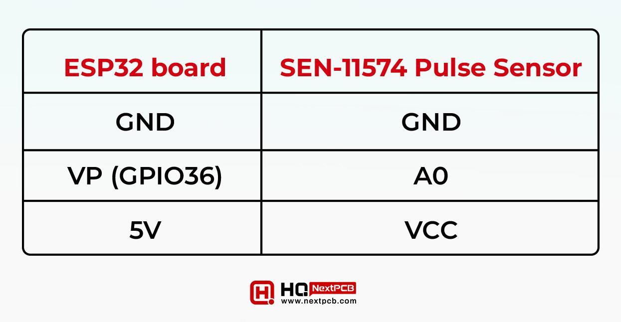
Interfacing Pulse Sensor with ESP32
To complete the circuit, we need three components:
- ESP32 board
- SEN-11574 pulse sensor
- Connecting Wires
There is a need to connect the SEN-11574 sensor’s pin with the ESP32, and the map of this connection is present in the table given below:
|
|
|
|
|
|
|
|
|
|
|
|
The same connections are indicated in the diagram given below:
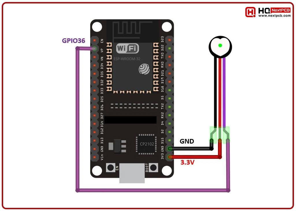
As mentioned before, the operating temperature of the pulse generated is between 3.3V to 5V; therefore, we’ll connect its Vcc pin to the 3.3V pin of the ESP32. By the same token, the ground terminal is connected, as shown in the above figure. The analogue signal pin is connected here with the ADC_CH0 pin i.e. GPIO36 of the ESP32. Once the circuit is formed in such a way, then we can move towards its coding part.
Installing ESP32 Libraries
The ESP32 is programmed in the Arduino IDE, and it is always advisable to use the latest version for the best performance. If you are using it for the first time, then you have to install the ESP32 microcontroller board in it. For this, follow the steps mentioned below:
- Open the Arduino IDE.
- Create a new project.
- Go to Sketch>> Library > Manage Libraries.
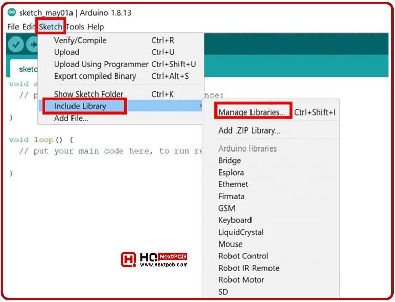
- After clicking the following window will open in front of you:

- The window shown above is used to search the libraries and in our case, we want to add the pulse sensor library therefore, type “pulsesensor” and then hit enter to search it. In my case, the following screen is shown:
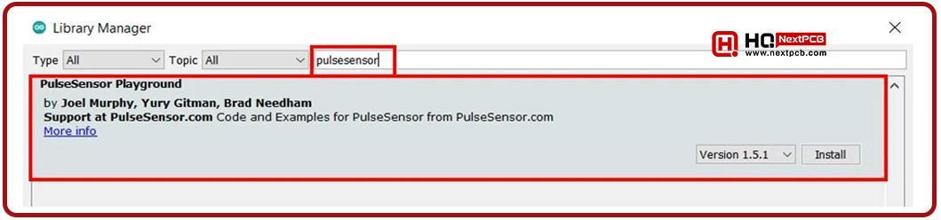
- I suggest you install the latest version. Once you find it, hit the “install” button and wait for the installation.
- Once installed, you have to restart your IDE so it may work well.
Now your Arduino IDE is ready to run our project.
ESP32 with Pulse Sensor - Programming Code
Now, let’s see some examples to understand the workings of this sensor library. Arduino IDE has some examples that help the user to practice this pulse sensor. These are the built-in codes and can be used directly without using any manual logic.
Detect Heart Rate with Pulse Sensor and ESP32
We are going to start with a basic example. This project is about detecting the heart rate with the ESP32 and pulse sensor (as we have been talking about since the beginning). Here, you will control the on-board LED of the ESP32 to align with the heart rate.
Arduino Sketch
The hardware of this sensor is ready, and the only step is to create the code to control the hardware. To do this, let’s follow the steps given below:
- Open the Arduino IDE.
- Create a new project.
- from the above menu, search for File > Examples > PulseSensor Playground > GettingStartedProject.
- After this, the code given below will be open in the Arduino IDE:
|
|
The purpose of this code is to blink the LED light of the ESP32 in synchronization with the heartbeat of the user. The heartbeat is sensed with the heartbeat sensor. The code given above is designed to work with the Arduino IDE, but as we are using the ESP32 in the project, we need to modify just two lines of the code to make it compatible with the hardware we have just designed. After this, the code will be perfectly ready to work with the ESP32. The changes are:
- Set the PulseSensorPurplePin from 0 to 36 in the code because, in our hardware, the signal pin is connected to the GPIO Pin 34 of the ESP32. The resultant code line will look like
|
|
- The ESP32’s built-in should be connected to pin 2 therefore, change it from 2 to the GPIO13 to variable 2. The following line will help you to understand this:
|
|
Another change required to make the project ready is to set a suitable threshold value which is 550 in our default code but I would like to change it because the current value is according to the Arduino (where the ADC range is 0-1023) but in case of ESP32 the ADC values are 0-4095. So paste the following line in place of the current line:
|
|
Now, the code is ready for our project.
Code Working
Now, I am going to divide the code into different parts to demonstrate the workings of the code. Here is the detail for each part:
|
|
At the start of the code, the variables are defined and their values are set including the GPIO pin (the one we have changed in the step above). The value of the LED13 pin is set to 2, we are declaring the variable named "Signal,” and the fourth line indicates the threshold value that we have just modified.
Setup Function
The setup function is the one that runs only once in the code. Here, we are declaring the baud rate at the start. For this experiment, we are using the 9600 baud rate:
Serial.begin(9600);
In the same function, we wish to set the pin of pin 13 to output because we want to blink as our output; therefore, we are using the line given below:
Loop Function
The loop function is the part of the code that will execute continuously until the logic allows it. Here we wish that the analog pin is read continuously; therefore, the following logic is utilized here:
Signal = analogRead(PulseSensorPurplePin);
The values are saved in the variable we’ve declared before. In the next step, these values are shown on the screen using the Print function:
Serial.println(Signal)
The subsequent section of the code continuously compares the signal value with the threshold values using an "if-else statement". As a result of this, the LED turned on or off according to the comparison. It is on only when the signal value is on. To indicate the change, a delay of 10 milliseconds is added to prevent rapid toggling of the LED state in response to small fluctuations.
Heart Beat Monitoring Results
Once you understand the code, it is time to upload it to ESP32. The built-in code is already present in our file, but before running it, some points must be kept in mind.
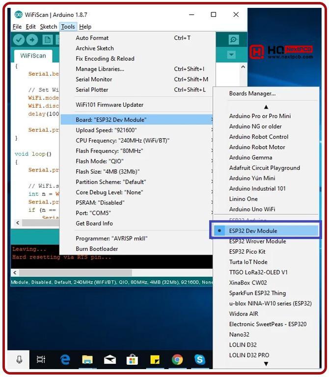
- Check that the right board is selected. For this, go to Tools > Board and check if the ESP32 is selected.
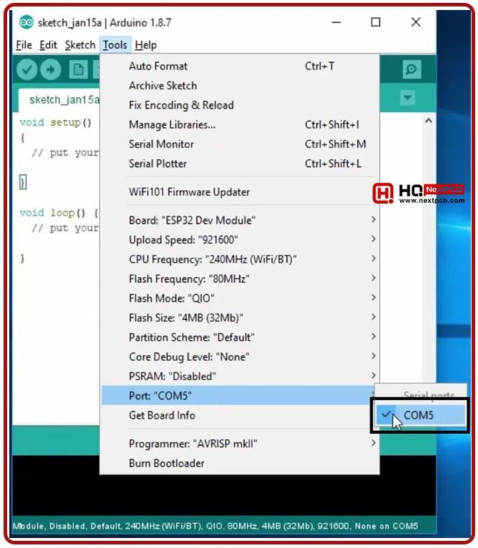
- It is important to check if the right COM port is selected. For this, you have to see Tools > Port.
- If both of these are right, then the code is ready, and you can run the program. Once it is fed into the ESP32, then it's time to test the sensor's performance.
- Hold the sensor between your fingers and keep in mind that the pressure must be applied gently. You do not have to press it firmly, but just show the finger in such a way that the LED may detect the pressure of the blood vessels.
- Now, observe the built-in LED of the ESP32, and you will see the light start blinking according to the blood pulse rate.
In some cases, if the LED does not blink properly then, have to change the threshold value according to the model of ESP32 or other technical changes.
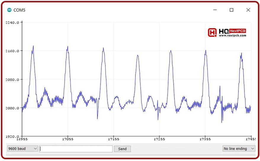
ESP32 Plotting Heart Beat Signal
We are now plotting the same signal (retrieved from the pulse sensor) on the serial plotter. The same signal will be used to plot a graph and will show the pulse of the user in a more user-friendly way. Follow the steps to get the required output:
- Go to Tools > Serial Plotter and start the serial plotter. Now, set the baud rate to 9600, as we have fixed in the code.
- Keep in mind that the finger must be in the right place on the pulse sensor with the right pressure.
- The signals will take multiple values and in the start, they will be unstable for a while but wait for the signal to stabilize, and after that, you will see the wave like the following:
So, that was all for today. I hope now you can easily design this Heart Beat Monitoring Project with ESP32. If you have any difficulties, please ask in the comments and we will resolve your issues. Thanks for reading. Have a good day.
Comment