Hello friends, I hope you all are doing well. In today’s tutorial, we are going to design a Line Following Robot using the ESP32 Microcontroller Board. A Line Following Robot is an autonomous robot(normally a 3-wheeler robot) that follows a dark line on a white surface. Such robots are normally used in industries to perform different tasks(i.e. pick & place objects) on a fixed track. Line Following Robots are also used in restaurants to take orders and deliver food. It also has some applications in the toy industry.
To design this Line Following Robot, we are going to use an ESP32 Microcontroller Board. The output of this project is shown in the below figure:
You should first watch this video to understand the robot’s working:
Project Overview/Working
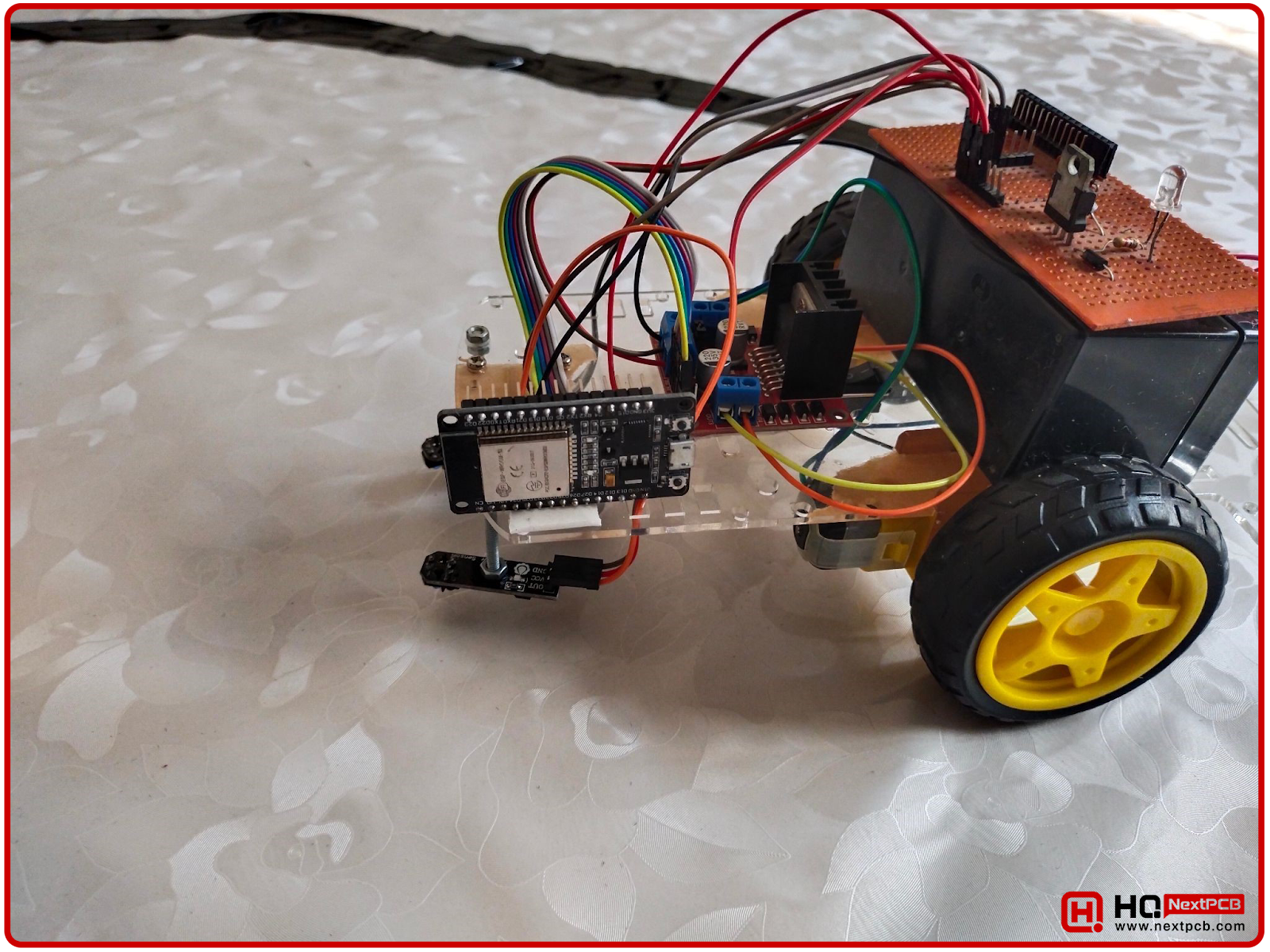
Today, we are going to design the Line Following Robot, shown in the below image:
When light falls on a white surface, it gets reflected while the black surface absorbs the light. It’s the main principle behind the Line Following Robot. The arena of a Line Following Robot normally has either of these 2 settings:
Components Free Worldwide Shipping
- A Dark Line on a white surface. (mostly used)
- A White Line on a dark surface.
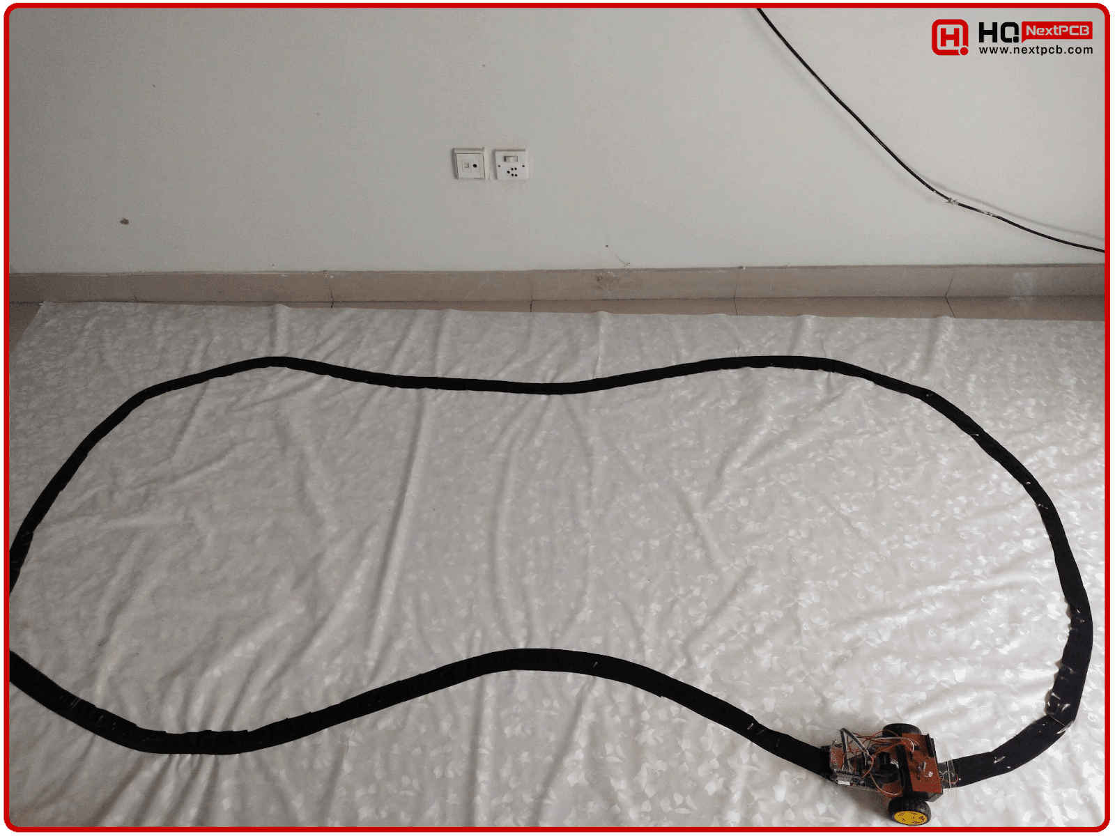
In our project, we have used the first approach, so our robot will follow a Dark Line on a white surface. To design the arena, we used a simple white sheet as the surface and used duct tape to draw the line. Our arena for the Line Following Robot is shown in the below figure:
Line Following Robot - Hardware Design
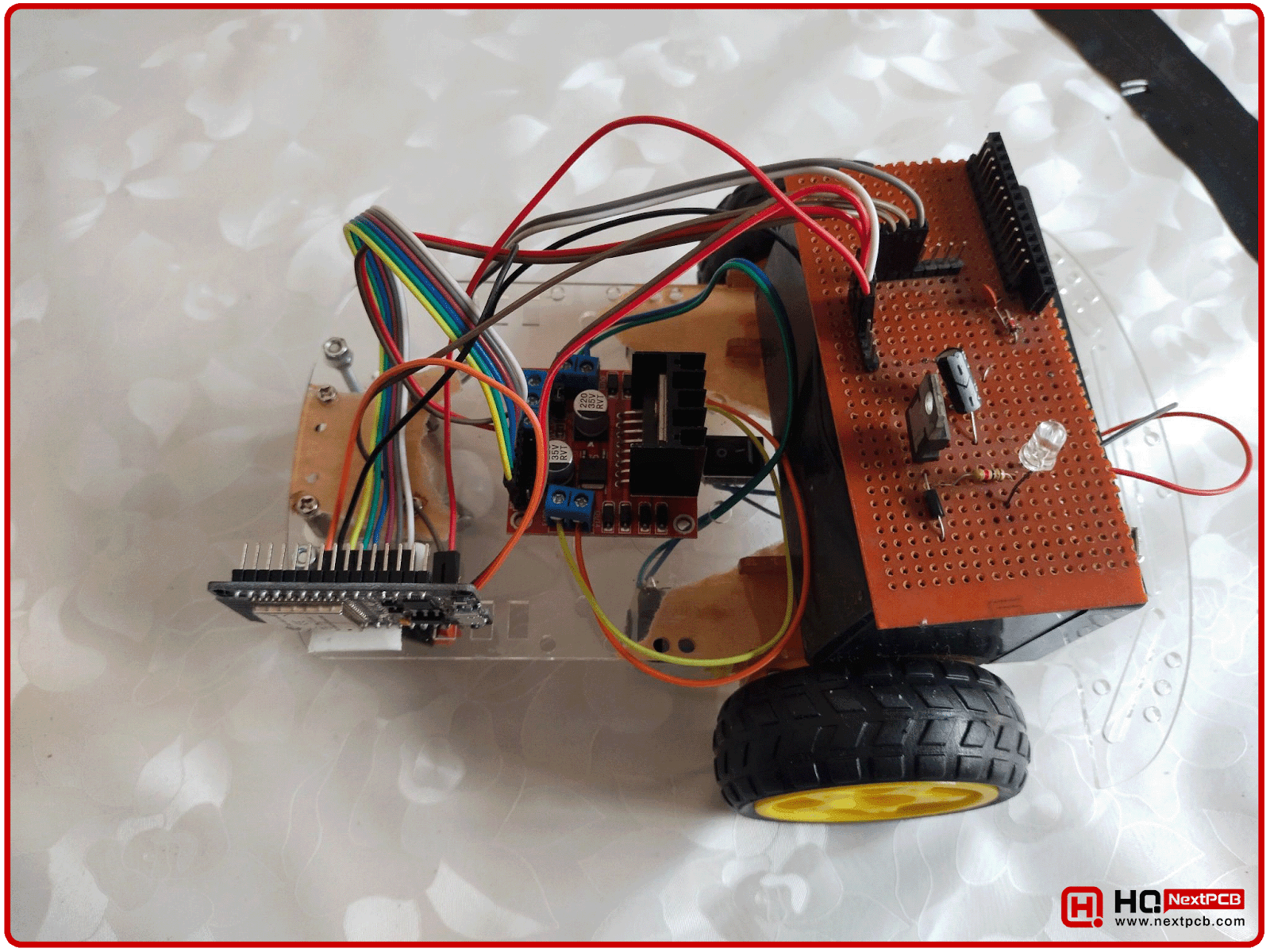
Now, we are going to design the Line Following Robot itself. We will discuss the components working and placement on the robot, one by one. The top view of our Line Following Robot is shown in the below figure:
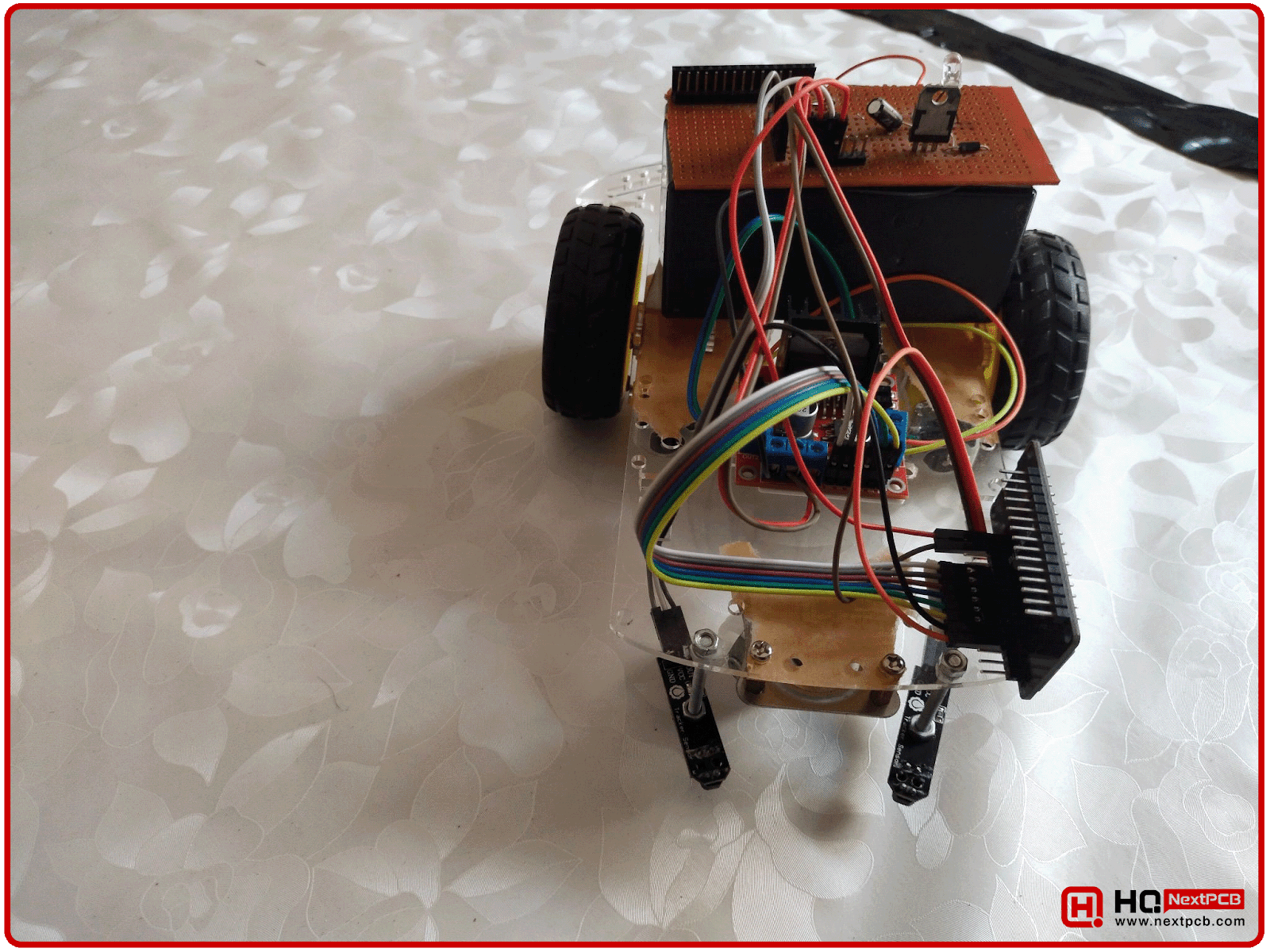
Here’s the Front View of the Robot:
Line Tracking with IR Sensors
We need to place IR Sensors at the bottom of our Robot to track the dark line. We have used the below IR Transceiver Sensors(having transmitter & received on a single chip):
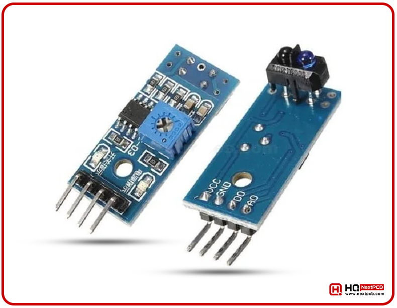
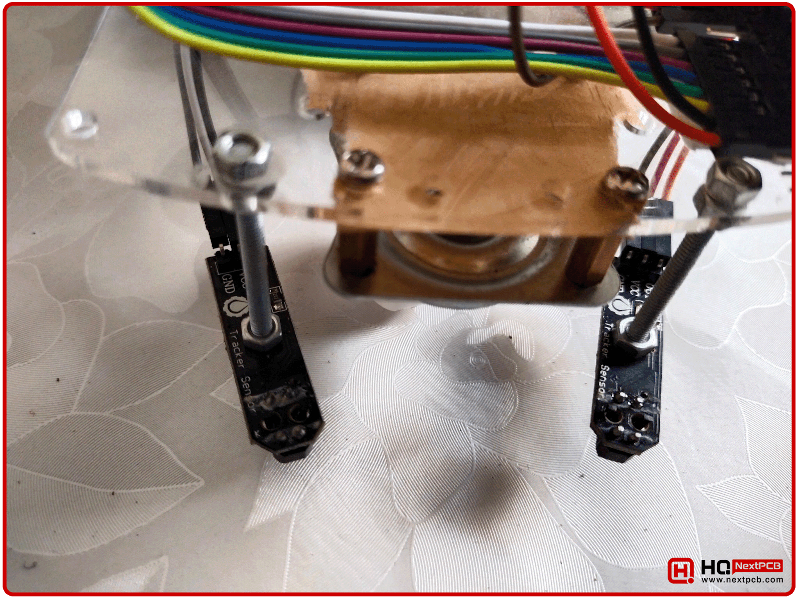
We have placed 2 IR Sensors on the front side of the robot, in a way that the dark line lies in between these sensors. The sensors placement on the robot is shown in the below figure:
During robot motion, if the IR sensor is positioned above the dark line, the receiver won’t get the reflected infrared rays and the sensor will get LOW, but when the sensor comes above the white surface, the infrared ray will get reflected, and received by the IR receiver and the sensor output will get HIGH.
So, by utilizing this IR Sensor behavior, we can devise the below logic:
- When the left IR sensor gets LOW, slightly lower the speed of the left motor.
- When the right IR sensor gets LOW, slightly lower the speed of the right motor.
- When any of these sensors get HGIH, increase the speed of the respective DC Motor.
By careful tuning of the DC motor speed change, we can make our robot to smoothly follow the dark line, as shown in the above video.
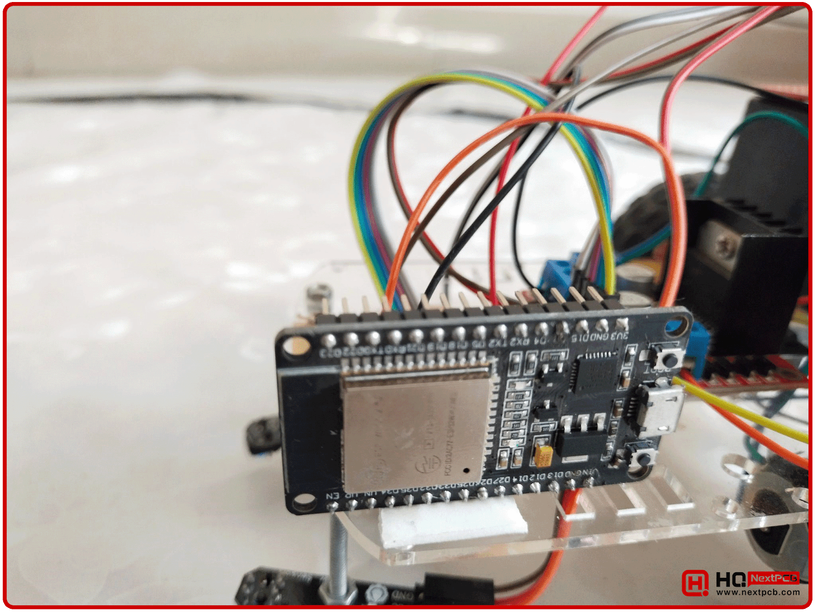
ESP32 Microcontroller Board
ESP32 Board is acting as the brain of the Line Following Robot. It will take data from the sensors and will operate the DC Motors accordingly. ESP32 is controlling the speed of these DC Motors with the help of Pulse Width Modulation(PWM). ESP32 Microcontroller Board, mounted on our Line Following Robot, is shown in the below figure:
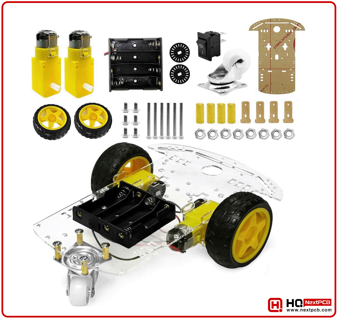
3-Wheller Robot
We have used the below Robotic Chasis for our Line Following Robot. As you can see in the below image, it has 2 DC motors attached to its rear wheels. These DC Motors operate at 12V and we will need a motor driver(i.e. ULN2003, L298, FET-based etc.) to control their speed and direction. In our case, we have used the L298 Motor Driver Shield to control these DC Motors.
Motor Driver L298
L298 Motor Driver Shield uses L298 IC as its core element and can control 2 DC Motors from a single shield. L298 Motor Shield is shown in the below figure:
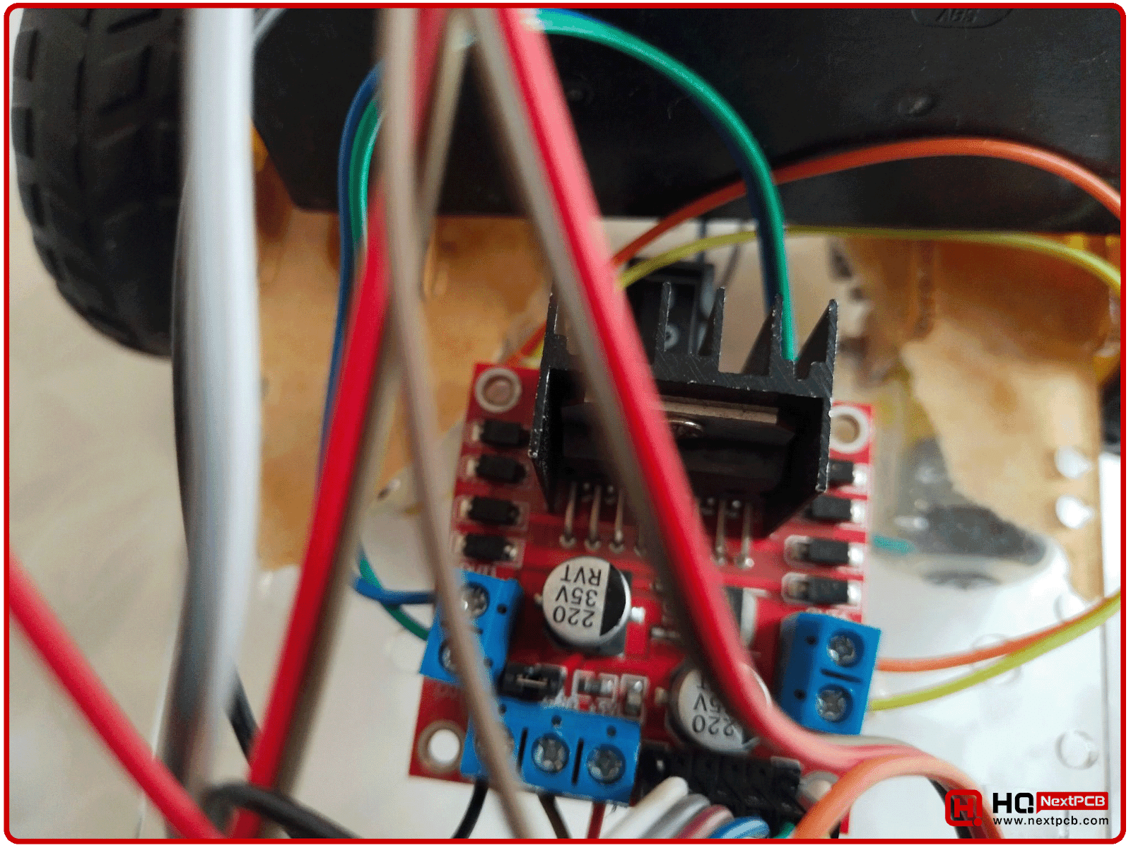
L298 Motor Driver Shield has 4 Inputs, 4 Outputs, 2 Enable and 3 Power Pins. As I said earlier, we can control 2 DC Motors with a single shield, the pinout is as follows:
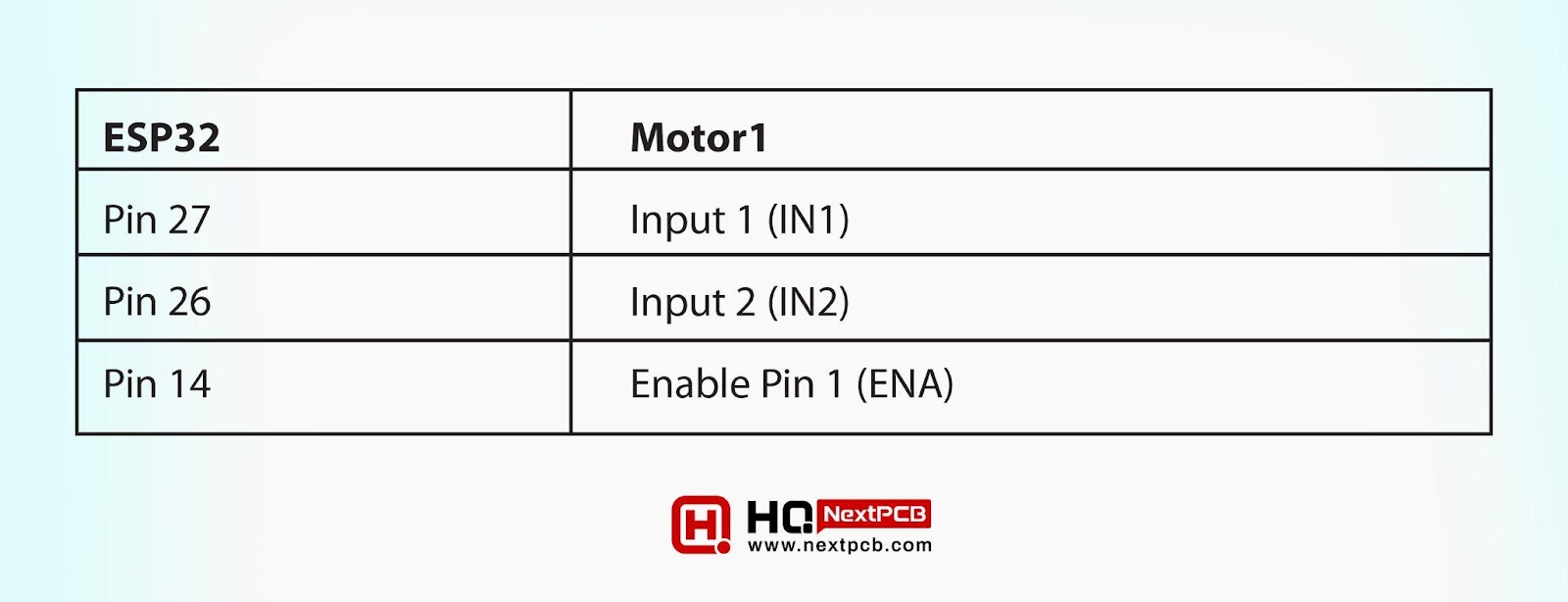
- Motor1 will be connected to 2 Output Pins(OUT1 and OUT2) and is controlled by the 2 input pins(IN1 and IN2) and 1 enable Pin(ENA).
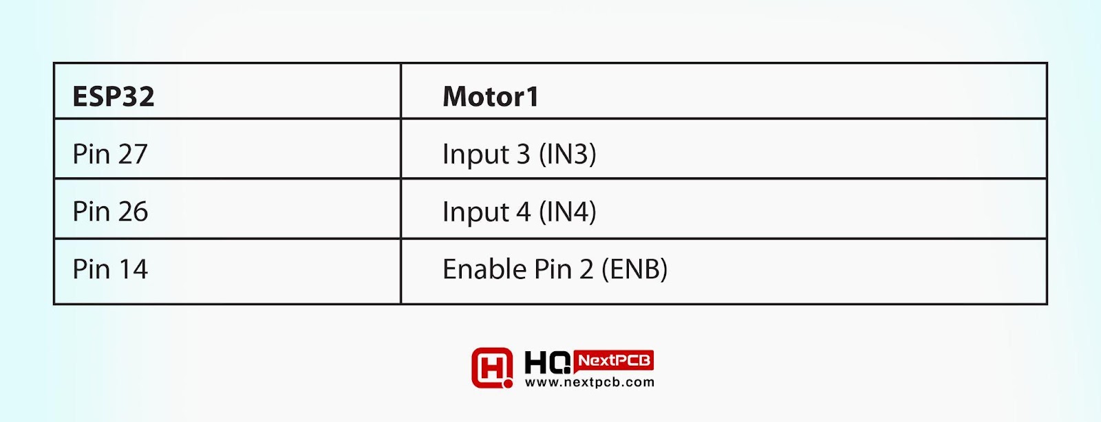
- Motor2 will be connected to the other 2 Output Pins(OUT3 and OUT4) and is controlled by the 2 input pins(IN3 and IN4) and 1 enable Pin(ENB).
The input and Enable Pins are controlled by the microcontroller, which in our case is ESP32. The functionality of these Pins is as follows:
- The Enable Pin is used to control the speed of the motor with the help of PWM(Pulse Width Modulation).
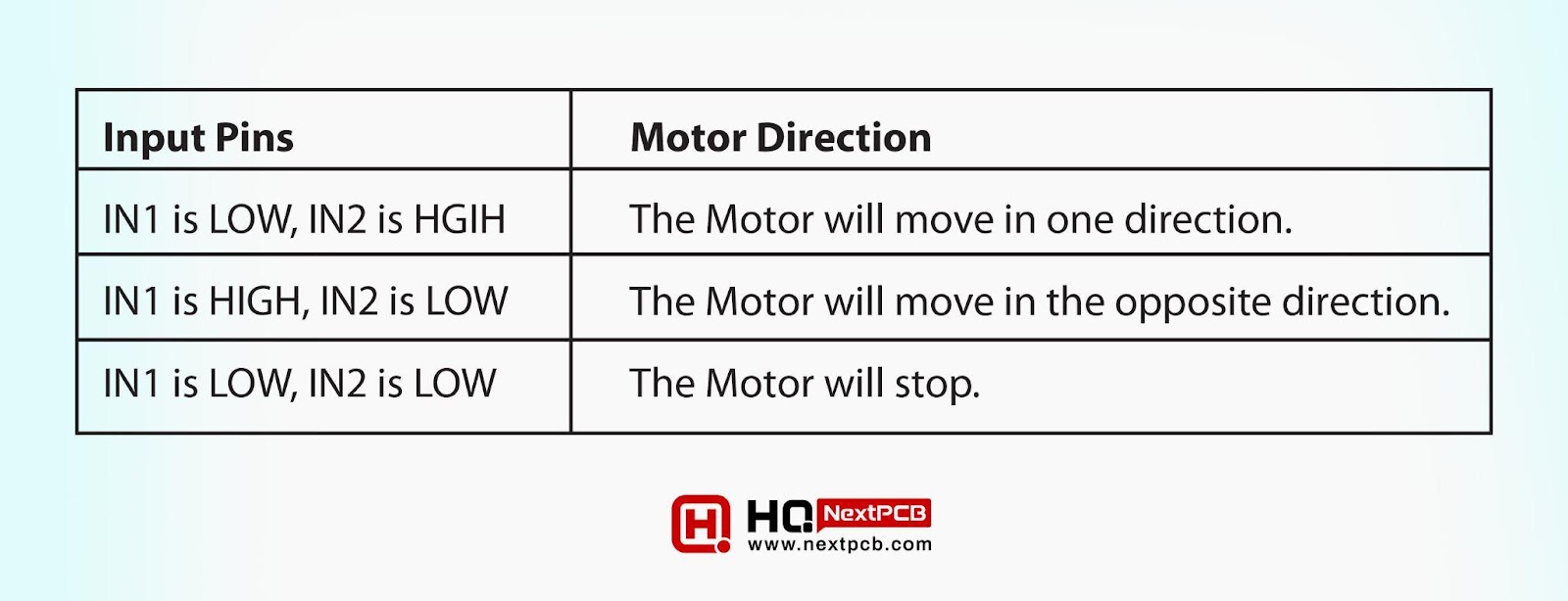
- The Input pins control the direction of the DC Motors, as shown in the below table:
|
|
|
|
|
|
|
|
|
|
|
|
We need to provide below 3 voltage levels to the L298 driver:
- +12V
- +5V
- GND
We will get the +12V and GND from the 12V battery but in order to provide the +5V, we need to design a voltage regular circuit with LM7805.
Voltage Regulator with LM7805
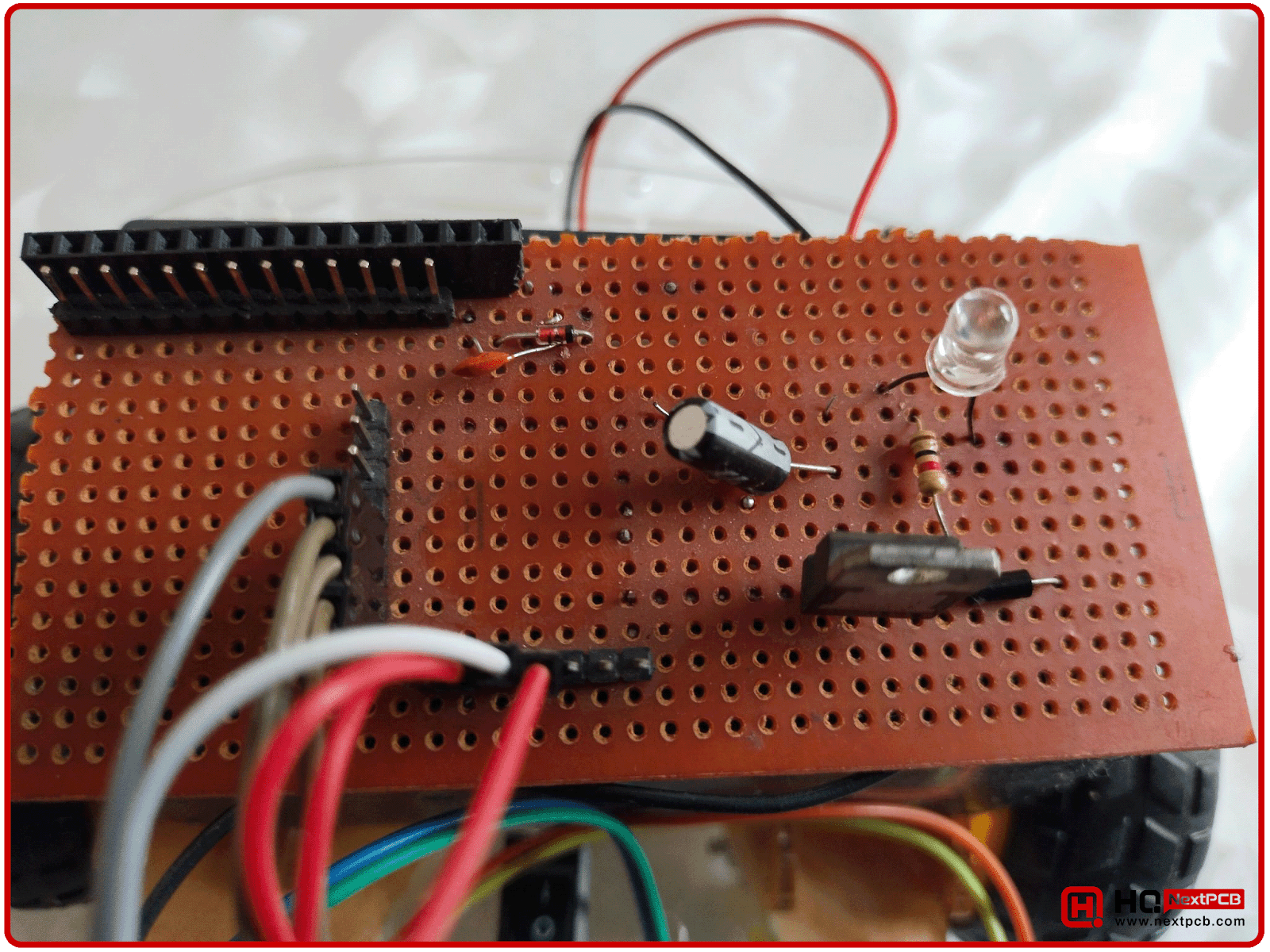
This voltage regulator will step down the 12V from the battery source to 5V. This 5V will not only be used in the L298 shield but will also be provided to ESP32 and IR Sensors. We will use the LM7805 to regulate the voltage from 12V to 5V, it's specifically designed for this purpose. So, we need to design this simple circuit:

Here’s the hardware setup of the voltage regulator with LM7805 on a Veroboard:
Components Used
Here’s the list of all the components used to design the Line Following Robot:
- ESP32 Microcontroller Board.
- DC Motors x 2
- L298 Motor Driver Shield
- 12V Battery
- LM7805 Voltage Regulator
- LED
- Resistor 1kohm
- Capacitor 100uF
Line Following Robot - Circuit Diagram
Here’s the complete circuit diagram of the Line Following Robot:
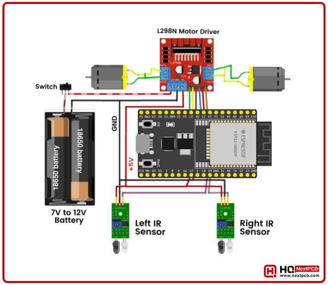
We have designed this circuit and placed it on the robotic chassis. The gap between the IR Sensors must be greater than the width of the dark line, so be careful while placing these sensors on the robot.
Here’s our line following robot equipped with all electronic components and now it is time to write the programming code for ESP32:
Line Following Robot - Programming Code
We have designed the ESP32 programming code in Arduino IDE. Here’s the complete code:
|
|
Now let’s understand this programming code, step by step:
Variables in ESP32 Code
At the code start, we have initialized the variables, which we will use in the code later:
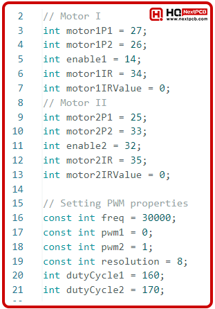
Let’s extract the Pinout from the above code. The ESP32 connection with the First Motor is shown in the below table:
|
|
|
|
|
|
|
|
|
|
|
|
The pinout of Second Motor with ESP32 is shown in the below table:
|
|
|
|
|
|
|
|
|
|
|
|
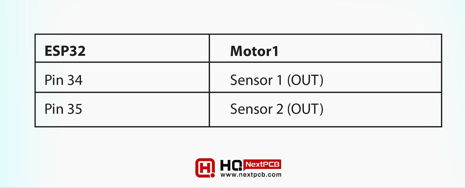
Finally, the pinout of IR Sensors with ESP32:
|
|
|
|
|
|
|
|
|
Moreover, we have used two variables motor1IRValue and motor2IRValue to save the values from IR sensors.
Lastly, we added few variables to initialize the PWM Channels, aswe are working with 2 DC Motors, so we introduced 2 PWM Channels.
Setup() Function in ESP32 Code
ESP32 Setup() Function is shown in the below figure:
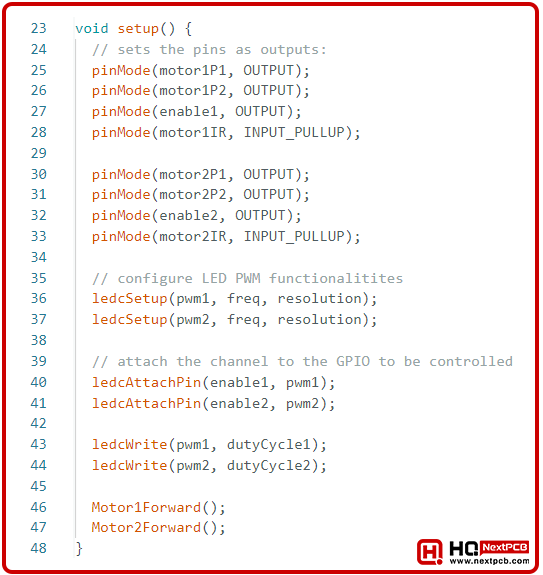
In the above code, we have first set the pin Mode of all DC Motor Pins to Output, aswe will be sending commands from ESP32 to these DC Motors.
As we will be receiving data from the IR Sensors, so we have set IR pin to INPUT_PULLUP. Software pullup is recommended for inputs as it removes the noisy signals.
Next, we configured the PWM Functionality by providing the frequency and resolution to the PWM channels. These PWM channels(pwm1 and pwm2) are attached to the Enable Pins of L298 motor driver and we have also assigned the duty cycle to these pins.
At the end of the setup loop, we have called two functions to move the Motors in the forward direction. Let’s have a look at these functions:
Motor Forward Functions
We have created separate functions to control the motors, shown in the below figure:
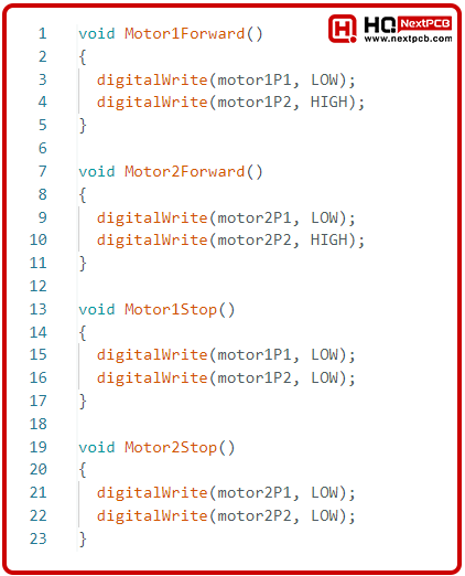
As you can see in the above figure, to move the motors in forward direction, we have set the Input 1 to LOW and Input 2 to HGIH. If your motor moves in the reverse direction, simply reverse the logic. Moreover, to stop the motor, we have simply made both of its Inputs LOW.
Now, let’s have a look at the Loop Function:
Loop() Function
The Loop function of Line Following Robot is shown in the below figure:
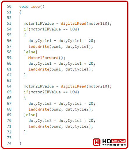
Here, we are reading the values of IR Sensors. If the value of the IR Sensors gets LOW, means the motor on its side is moving a faster than the other motor. So, we are simply lowering its speed down by reducing its duty cycle. The duty cycle should have value between 0 to 255.
Now let’s upload the code in the ESP32 board and check the results:
Line Following Robot - Results
Our robot is now ready to follow the dark line, so place your robot in the arena and make sure that the dark lines comes exactly in between the IR Sensors. Now turn the power ON and if everything goes fine your robot will start following the black line.
Currently, our robot is only following the black line. In the upcoming lectures, we will add more advanced features in our robot. For example, we can add obstacle avoidance capability in our robot. We can also add the feature of turning back, instead of moving in a circle. So, there’s a lot more cool stuff that we will apply on this Line Following Robot in our upcoming lectures.
So, that was all for today. I hope you guys have enjoyed today’s project. If you have any issues, let us know in the comments and we will try to resolve these issues as soon as possible.
Comment