Hello everyone, I hope you all are doing great. In today’s tutorial, we will interface ESP32 with DC Motor using an L298 Motor Driver. We will control both the speed and direction of the DC Motor and will use Arduino IDE to compile and upload code to the ESP32 Microcontroller Board. I’ve divided this guide into two parts:
- How does L298N Motor Driver work?
- How to control the speed and direction of the DC motor using ESP32 with the L298N Motor Driver.
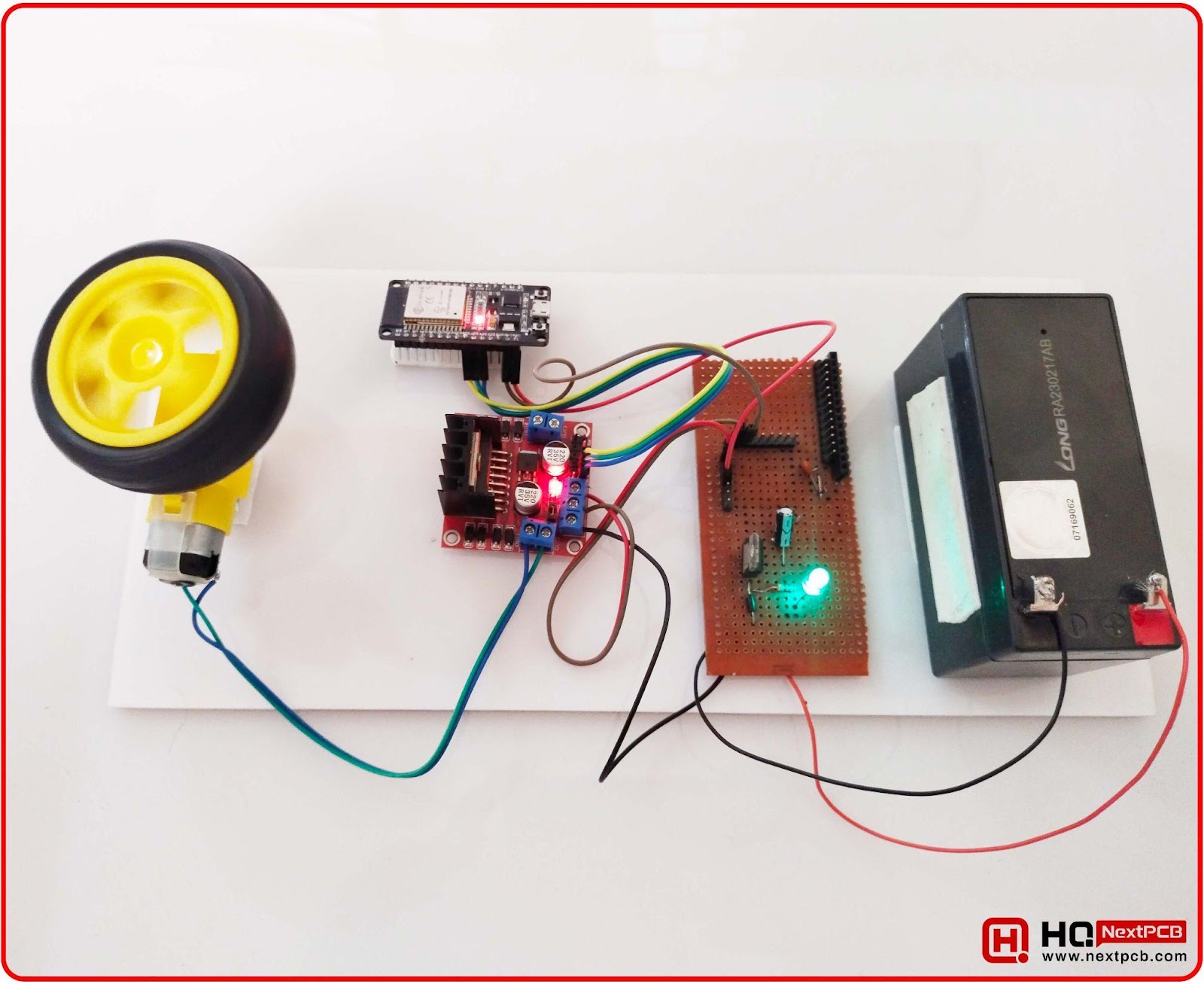
Among the different ways to control the DC motor, I selected the L298N motor driver as it's easy to interface and can handle heavy loads. Here, we’ll start the discussion by looking at some important prerequisites for this project. After that, I am going to show you the basic introduction to the L298N motor driver, where we’ll see its pinout and working. There will be a detailed description of the code, its explanation, and the wiring of the DC motor with ESP32. The complete project for DC Motor control is shown in the below figure:
Components Free Worldwide Shipping
ESP32 with DC Motor Pre-requisites
The project includes both software and hardware, so to have the right software system, you need to have an IDE to program the microcontroller. As discussed before, the ESP32 is programmed using the Arduino IDE, but if you are using it for the first time, you need to first Install ESP32 in Arduino IDE. To complete the hardware, you have to get all the components listed below:
Components Required
- ESP32 Microcontroller Board
- DC Motor(12V)
- L298N Motor Driver
- Power source (batteries)
- Jumper wires
Now, let’s first understand the working of Motor Driver L298N, as it's the main component in DC Motor controlling.
L298N Motor Driver Introduction
- The L298N Motor Driver is a high voltage, dual H-bridge motor driver module that is used to control and drive DC and Stepper motors.
- We can control 2 DC Motors at a time with a single L298 module.
- We can control both the speed and direction of these DC motors. Direction is controlled by polarity reversal, while the speed is controlled with a PWM signal. (We will discuss it below in detail)
- The module has two H-bridges to make it able to control two motors at a time.
- L298 has a wide range of voltage ranging from 5V to 35V, making it a versatile driver.
- It uses the following techniques to control the DC motor:
- The PWM controls the motor’s speed.
- The H-bridge controls the motor's rotation.
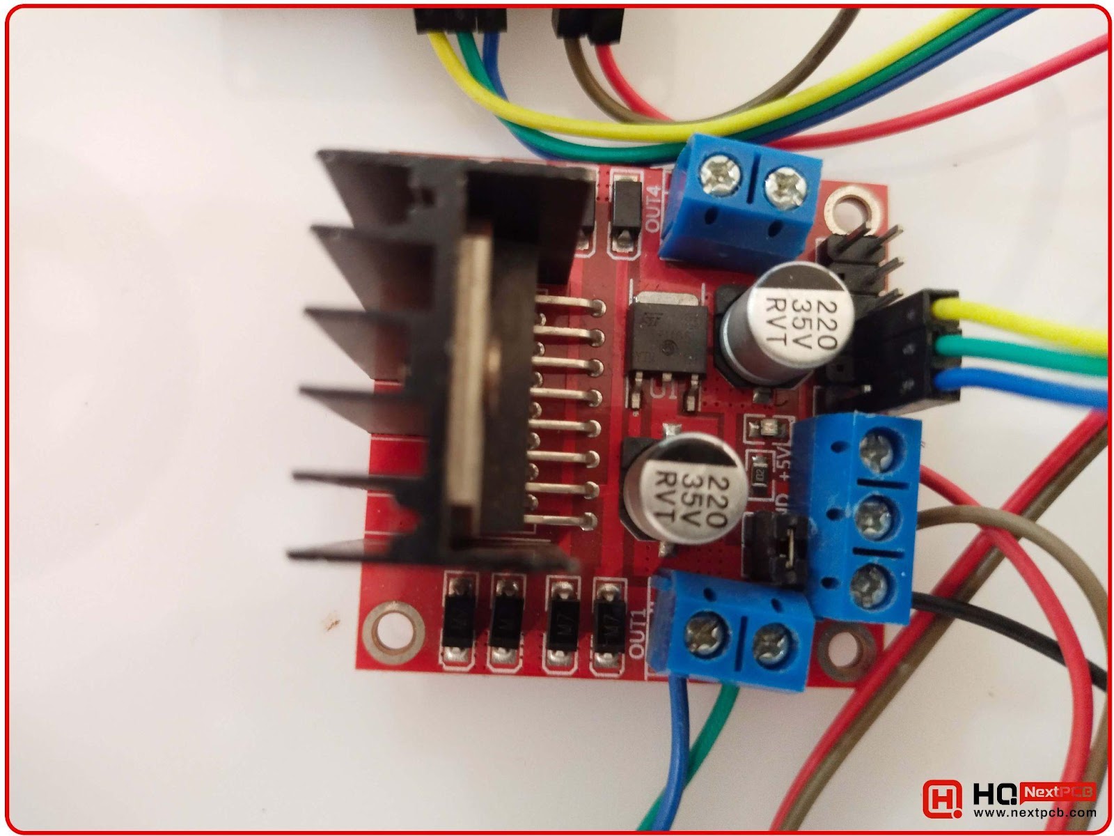
Here’s our L298 module to control the DC Motor:
L298N Motor Driver Pinout
The image below shows the pinout along with its labels on the L298N motor driver:
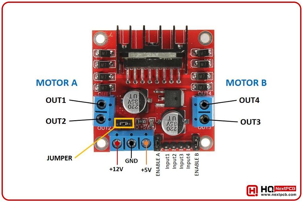
Here is a brief description of each label:
L298N Motor A and Motor B
In the image given above, motor A and Motor B represent the slots where the motors are attached. I have aforementioned that it can control two motors at a time, so each of them is attached to these slots. Each side (left and right) of this driver has separate pinouts for each motor to provide a clean and interference-free structure.
- Motor A will be connected to OUT1 and OUT2.
- Motor B will be connected to OUT3 and OUT4.
These terminals are used to control the rotation of the motors.
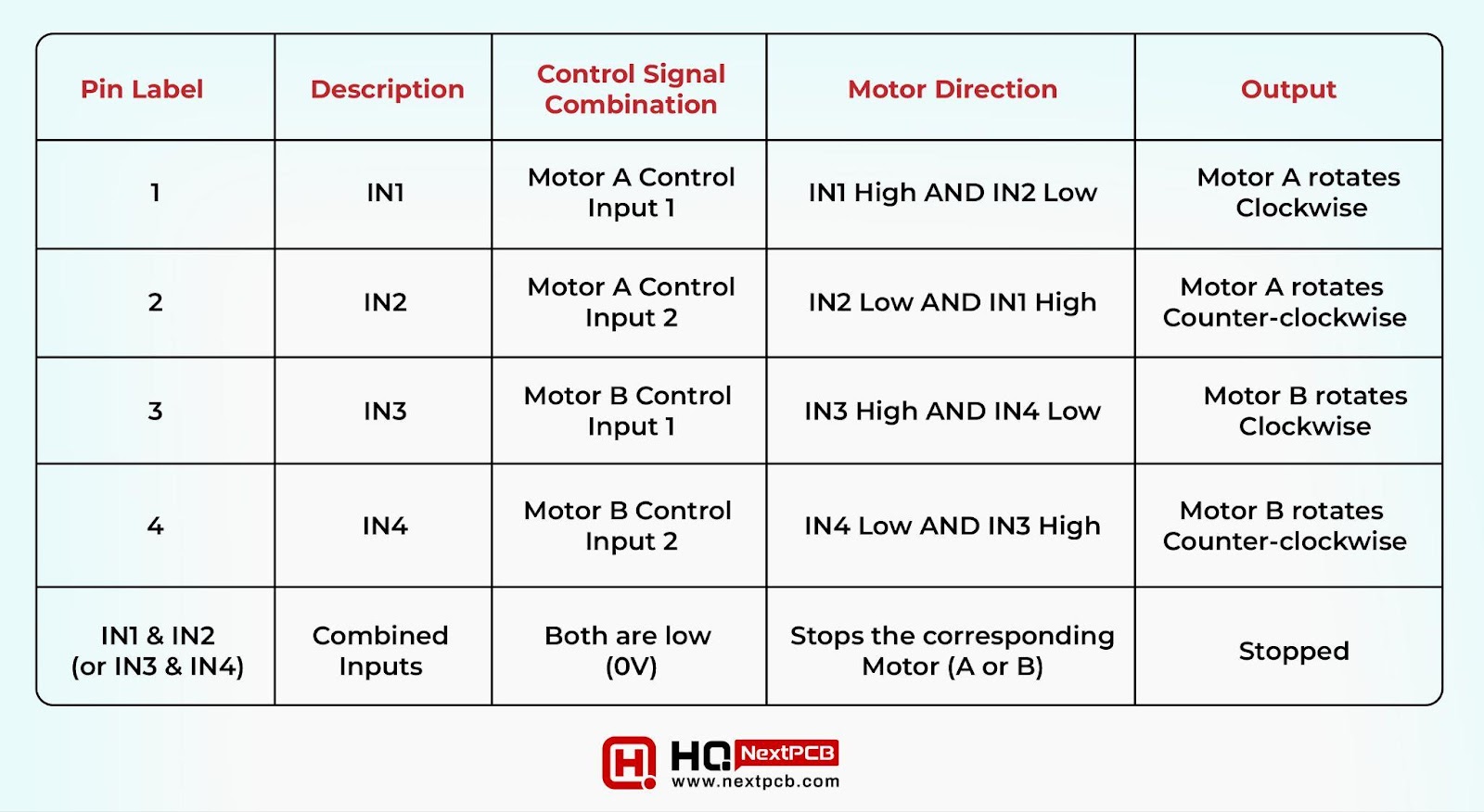
L298N IN1, IN2, IN3, IN4 Pins
These are referred to as the input pins of the motors because they are responsible for the direction of motor rotation. The structure of the L298N is designed so to work on the specific logic levels of these inputs. Hence the combination of these inputs allows a particular action of the motors. The table given below will explain each possible logic level and its outputs:
|
|
|
|
|
|
|
|
|
|
|
|
|
|
|
|
|
|
|
|
|
|
|
|
|
|
|
|
|
|
|
|
|
|
|
|
L298N Enable A and Enable B Pins
The enable A and enable B pins are assigned to the corresponding motors and enable or disable the control of the motors. Usually, these are connected to the microcontroller’s pulse width modulator (PWM) and therefore, control the speed of the motor according to its signals.
The HIGH or LOW voltage (5V to 0V respectively) on these pins determines if the IN pins will get the signals or not.
L298N Jumper
The L298N motor driver has internal and external voltage sources. The jumper is designed to select the voltage source of the internal L298N chip of the driver. The states of the jumper and their output are as follows:
- When the jumper is ON, it allows the 5V power supply to the external devices (maybe the microcontroller).
- When the jumper is OFF, it does not provide any power to the external device.
As a result, the state of this jumper is important to turn the power on or off for the circuit if there is no other power source for the external device connected to the circuit.
L298N Power Terminals
In the image above, you can see there are three power terminals:
- The GND is the ground connection of the L298N motor driver. It should be connected to the ground terminal of the power supply.
- 12V is the positive power supply of the terminal. Here, the voltage ranges from 5V to 35V. Yet, 6V to 12V is the recommended power supply range.
- The 5V power pin provides the 5V power supply to the external devices, such as the microcontroller connected to it. It has a limited current supply.
In case you want to supply more power than 12V, then there is a need to remove the jumper to supply the 5V power to the 5V terminal.
For this project, I am going to use 4 AA 1.5V batteries to get the 6V power supply. I recommend you use it the same way, but you can change it according to your available options.
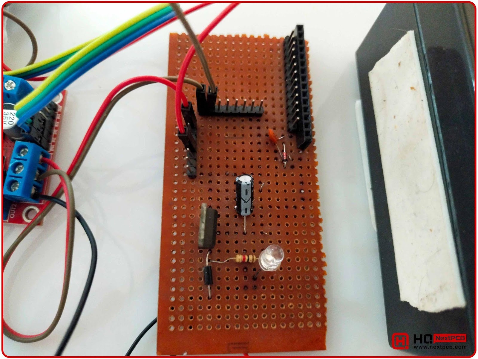
Voltage Regulator with LM7805
This voltage regulator LM7805 is used to reduce the voltage from 12V to 5V. This 5V will be used to power up both ESP32 and L298. So, we need to design this simple circuit:
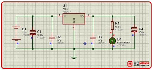
We have designed this LM7805 Voltage Regular Circuit on the Vero board, shown in the below figure:
DC Motor Control with the L298N Motor Driver
It is time to control the DC motor with the L289N motor driver because now we are familiar with all the functional pins that we are going to use in this project. In the first part, I am going to show you how to set the driver's pin to control the single motor. Let’s divide the procedure into different steps:
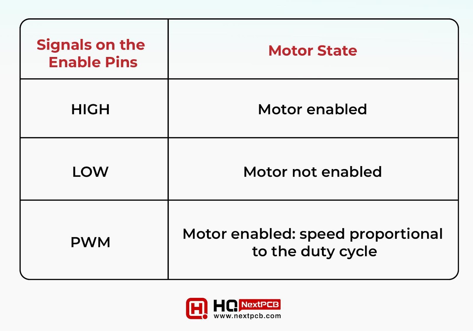
Step 1: Setting the Enable Pins
We’ve seen the general working of the enabled pin and understood that these work as the ON or OFF switches of the motor. The state of these signals is controlled through the coding of the ESP32. The following table will help you understand how the enable pins affect the signal motor in the project:
|
|
|
|
|
|
|
|
|
|
|
|
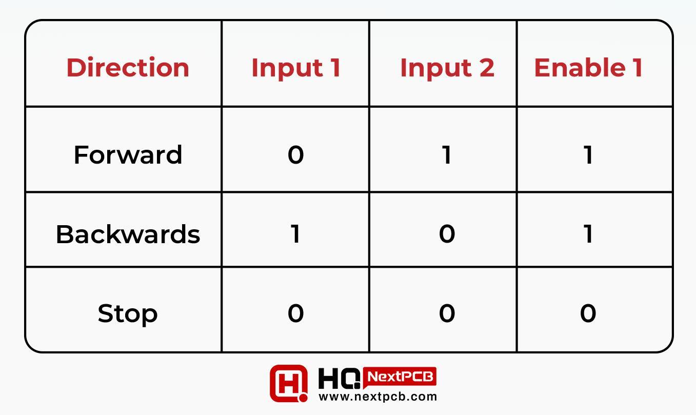
Step 2: Setting the Input Pins
Before this, we had seen the generic way of the L298N motor driver but here, we are going to control only one motor therefore, we have to understand how input 1 and input 2 control the direction of the motor. I’ve created a table to show you how to use inputs 1 and 2 (associated with motor A) to control the output:
|
|
|
|
|
|
|
|
|
|
|
|
|
|
|
|
|
|
|
|
Control 2 DC Motors with L298N
The L298N motor driver can be used to create the robot car using its feature to control two motors at a time. The combination of the motor rotation in different directions allows the robot to move forward, backward, left, or right. For instance, to move the robot forward, both the motors should move in a forward direction. Similarly, the opposite process is used to move the robot backward.
In case the user wants to move the robot in one direction (left or right), the opposite side’s motor has to spin speedily. To explain this, I have created a table that shows all the combinations and their output:
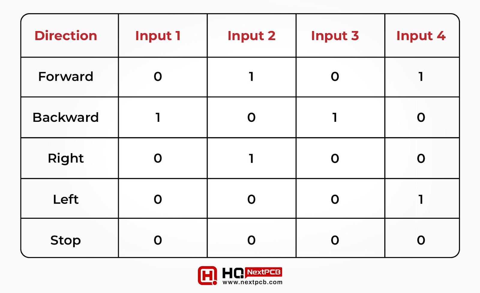
|
|
|
|
|
|
|
|
|
|
|
|
|
|
|
|
|
|
|
|
|
|
|
|
|
|
|
|
|
|
|
|
|
|
|
|
ESP32 with DC Motor and L298N Motor Driver Wiring
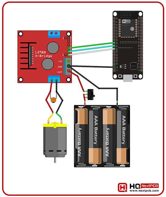
Now, that we know all the basics, let’s try an example of controlling motor A with the L298N motor driver. Here, we are using the ESP32 to handle the motor rotation and for this reason, we have to create the connection between ESP32 and the driver using the wires. As expected, you have to connect the Enable pin, input 1, and input 2 with the ESP32, and for your convenience, I have created a diagram for visual reference:
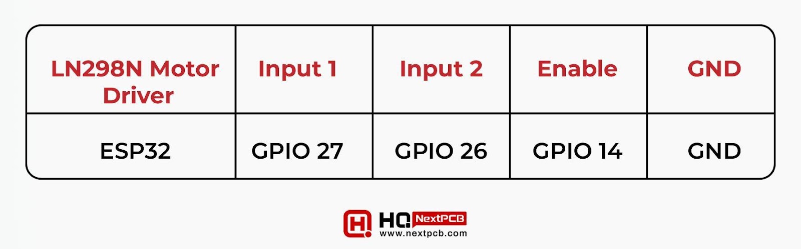
Once created, you can confirm the connection by matching it with the following table:
|
|
|
|
|
|
|
|
|
|
|
|
It's up to you if you want to change the GPIO pins; in my case, I found the mentioned pins most suitable. Here’s our hardware setup to control the DC Motor:

How to Power L298N Motor Driver
The DC motor requires a lot of current to work properly; therefore, there is a need for an external source. As we need a range of 6V to 12V, I have connected 4AA batteries. I’ve also used the switch between the battery holder and driver, but it has made my work easy to effortlessly cut off and on the battery supply.
Another additional component (optional) that I recommend is the capacitor, which will make the output smooth with the fewest spikes. I’ve attached a 0.1 uF ceramic capacitor for both terminals (positive and negative) of the battery.
ESP32 with DC Motor and L298N Motor Driver Code
Once the hardware part is ready, the ESP32 needs the code to work accordingly. Recall that the signals on the ESP32 pins control the rotation of the motor, so, let’s set the ESP32 to work according to our project. Prior to starting the project, I want to share the list of prerequisites that are extremely important if you are using ESP32 coding for the first time.
ESP32 Coding Pre-requisites
- Make sure you have the Arduino IDE to use the code for ESP32.
- Install the board of ESP32 in the Arduino IDE.
- You are using the right board (ESP32) and port (depending on the ESP32 model) while coding.
- The ESP32 is connected to the PC or computer you are using.
- You know that once the code is ready, you have to press the ESP32 board’s button to feed the code into it.
- The hardware part of the project is ready.
ESP32 Code Control DC Motor
The following is the ready code that will be used to design the ESP32 to run motor A. This is the most basic code, and you can modify it, but if you are a beginner, I recommend you run it as it is at the start.
|
|
Let’s divide the code into different parts to explain the purpose of each part.
ESP32 Code for DC Motor - Pin Declaration
The code starts with the declaration of the ESP32's GPIO pins according to the hardware connection. For this, the pattern is to declare the variable type, its name, and then the GPIO PIN as shown in the code:
|
|
Make sure these numbers are the same as the hardware connection. The variable name may be changed according to the user’s choice.
ESP32 Code for DC Motor - Setting PWM Properties
As mentioned before, the PWM of the L298N driver controls the DC motor speed, which is directly proportional to the duty cycle. In this part of the code, the necessary parameters and their values are assigned for the PWM.
|
|
You can change the duty cycle value according to your choice but keep the DC motor properties in mind. The values must lie between the range of 0 to 255. If you are using the same frequency, then a value less than 200 will not be suitable and create a buzzing sound instead of properly working.
ESP32 Code for DC Motor - setup()
The next part is the setup() function. It has a code that will run only once; therefore, we are using the important declarations of the EPS32 here using the variable we have defined before it. In the first part, the output pins are declared:
|
|
A function ledcSetup() is used to configure the PWM signal with all its properties. It is a pre-defined function therefore, we simply have to use the parameters of PWM as an argument in it:
|
|
Now, let’s use another predefined function, ledcAttachPin() where we are using the GPIO pins (from where we are supposed to get the signals) as arguments.
|
|
Keep in mind the values of these arguments that we have just declared.
ESP32 Code for DC Motor - Moving Forward
The loop() function of the code is the one that runs continuously. Here, we’ll declare the instruction for the motor direction so we can change the direction anytime while dealing with this motor. The following lines are responsible for moving the robot in the forward direction:
|
|
ESP32 Code for DC Motor - Moving Backward
To move the robot backward, the user simply has to change the values of the motor pins:
|
|
ESP32 Code for DC Motor - Stop
There are two ways to stop the motor, we can either set the enable pin to LOW or set both inputs (1 and 2) to low. In our code, we used the second approach:
|
|
ESP32 Code for DC Motor - Motor Speed Control
To make the project more user-friendly, let’s alter the PWM signal duty cycle. For this, we are using ledcWrite() function. It accepts the pwmChannel and dutyCycle as arguments and works accordingly.
|
|
To use this in our code, we have chosen the while loop, and the resultant code is given next:
|
|
In case the while condition is no longer true, the previous duty cycle value which is 200 is used. You can see the limits of the while loop are kept at 255 and the function of ledcWrite is handling the process. The duty cycle increases by 5 after every iteration, but you can choose the value of your own choice. Here’s the final output of our project:
Have you noticed that at every step, when the user changes the direction of the motor, a message appears on the screen that the motor works according to our condition?
Conclusion
- In this project, we started learning how the ESP32 and L298N motor drivers can control the DC motor’s speed and direction.
- We understood that the L298N motor driver can handle two motors at a time and we understood the generic working and then saw the example where a single motor is controlled with this driver.
- The direction of DCotor spinning is controlled by input 1 and input 2.
- A table is defined for the different combinations of singles on these inputs and their resultant outputs.
- The PWM signal on the enable pin controls the speed of the motor spinning.
- The brain of this project is the ESP32, where the L298N motor driver helps to control the motor.
I trust I’ve covered all the points of this project that will help you to create the simple control of the single motor speed and direction with ESP32 sn the L298N motor driver
Comment