Introduction
DC voltage, or direct current voltage, is an essential concept in the world of electronics and electrical engineering. Unlike alternating current (AC), which constantly changes direction, DC voltage maintains a steady flow of electrical charge in one direction. This unidirectional flow of electrons makes DC voltage ideal for powering electronic devices that require a consistent and reliable source of power. DC voltage is its ability to store energy in batteries. Batteries, whether they are used in portable devices or as backup power sources, provide a stable and uninterrupted supply of DC voltage. This makes them indispensable in various applications such as powering remote sensors, emergency lighting, or even electric vehicles. DC voltage is also crucial in many electronic circuits. It is used to power microcontrollers, integrated circuits, and other electronic components.
By providing a constant voltage level, DC power ensures that these components function accurately and efficiently. Additionally, DC voltage is essential for controlling the speed and direction of motors in robotics, automation, and other mechanical systems. Understanding DC voltage is essential for anyone working with electronics or electrical systems. It is important to know how to measure, regulate, and manipulate DC voltage to ensure the proper functioning of devices and systems. DC voltage plays an important role in powering electronic devices, storing energy in batteries, and controlling various systems. Its consistent and unidirectional flow of electrical charge makes it an indispensable component in the world of electronics and electrical engineering.
DC Voltage Symbol
The representation of direct current (DC) voltage in electrical diagrams and circuit schematics involves the use of specific symbols to convey information about the nature and magnitude of the voltage source. One such symbol is the Unicode character U+2393, which appears as "⎓." This symbol is often employed to denote DC applications, signifying a constant and unidirectional flow of electric charge. Alternatively, a simple straight line is also utilized as a straightforward depiction of DC voltage.
DC Voltage Symbol
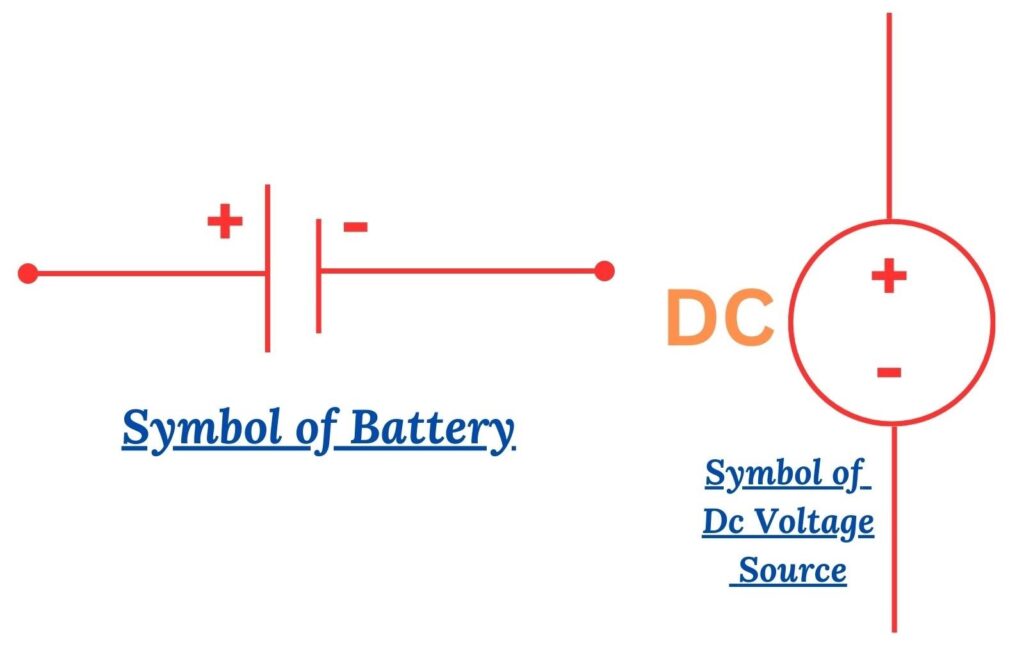
In circuit diagrams, various sources can be employed to generate DC voltage, with the most prevalent being the battery. The battery symbol in circuit diagrams consists of a set of parallel lines representing the constant flow of electric charge, typically arranged above a longer line that signifies the positive terminal. This widely recognized symbol efficiently communicates the presence of a DC voltage source, particularly when accompanied by an indication of voltage levels.
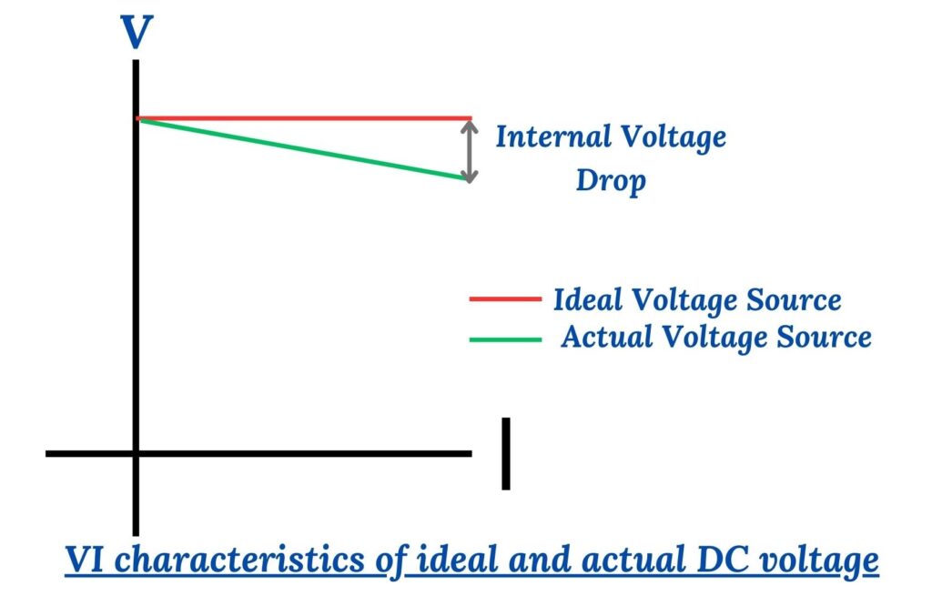
VI Characteristics of Ideal and Actual DC Voltage Source
Furthermore, another common symbol used to represent a DC voltage source in circuit diagrams is a straight line. This uncomplicated representation serves to convey the concept of a continuous and unidirectional flow of current. The absence of any alternating or oscillatory features in the symbol distinguishes it from symbols used for alternating current (AC) sources.
Components Free Worldwide Shipping
DC Voltage Wire Color Code
For DC (direct current) wiring, two prominent color coding schemes are widely recognized—namely, the IEC (International Electrotechnical Commission) DC Power Circuit Wire Color Codes and the US (United States) DC Power Circuit Wire Color Codes. The wire color code provides a standardized way of identifying the function of each wire in an electrical system. It helps electricians and technicians easily identify which wire is which, reducing the risk of errors and accidents. The DC voltage wire color code follows a specific pattern to indicate the function of each wire. Here are the commonly used colors:
IEC DC Power Circuit Wire Color Codes
The IEC (International Electrotechnical Commission) establishes a standardized system for DC power circuit wire color codes, defining specific colors for various functions within a DC power system. In the context of DC wiring, these color codes are crucial for ensuring consistency and clarity in identifying different wires and their respective roles. The following table outlines the wire colors associated with different components in a DC power circuit based on the IEC standard:
|
|
|
|
|
|
|
|
|
|
|
|
|
|
|
|
|
|
|
|
|
|
|
|
|
|
|
|
|
|
|
|
|
|
|
|
|
|
|
|
|
|
|
|
US DC Power Circuit Wire Color Codes
Another widely recognized DC voltage wire color coding system is defined by the US National Electrical Code (NEC), an essential standard for electrical installations in the United States. This system, also referred to as NEC, establishes guidelines for wire colors in DC voltage systems. Notably, the NEC does not provide specific color codes for ungrounded DC systems, deeming them unsafe for use according to their standards. The recommended wire color codes for DC voltage systems under the US National Electrical Code are outlined in the following table:
|
|
|
|
|
|
|
|
|
|
|
|
|
|
|
|
|
|
|
|
|
|
|
|
|
|
|
|
|
|
|
|
|
|
|
|
|
|
|
|
|
|
|
|
Difference Between DC Voltage and AC Voltage
When it comes to understanding electrical power, it's important to know the difference between DC voltage and AC voltage. While both types of voltage are used to power various devices and systems, they have distinct characteristics and applications. While DC voltage is commonly used in low-power devices and electronics, AC voltage is more suitable for high-power applications and long-distance transmission. It's worth noting that some devices, such as power adapters, can convert AC voltage to DC voltage to power electronic devices efficiently.
Here's a breakdown of the key differences between DC voltage and AC voltage:
|
|
|
|
|
|
|
|
|
|
|
|
|
|
|
|
|
|
|
|
|
|
|
|
|
|
|
|
|
|
|
|
|
|
|
|
|
|
|
|
How to Reduce DC Voltage
Reducing DC voltage is a common requirement in many electrical and electronic applications. Whether you need to power a low voltage device or protect sensitive components, there are several methods to achieve this. In this article, we will explore a few popular techniques for reducing DC voltage.
Voltage Divider: A voltage divider is a simple and cost-effective way to reduce DC voltage. It involves using a series of resistors to divide the voltage proportionally. By selecting the appropriate resistor values, you can achieve the desired voltage reduction. However, keep in mind that voltage dividers are not suitable for high current applications.
Zener Diode: A Zener diode is a specialized diode that can regulate voltage. It operates in the reverse breakdown region, maintaining a constant voltage drop across its terminals. By selecting a Zener diode with the desired breakdown voltage, you can effectively reduce the DC voltage to a specific level.
Voltage Regulator : A voltage regulator is a more sophisticated solution for reducing DC voltage. It is a dedicated integrated circuit that provides a stable output voltage regardless of input voltage fluctuations. Voltage regulators are available in various types, such as linear regulators and switching regulators, offering different levels of efficiency and performance.
Buck Converter: A buck converter, also known as a step-down converter, is a highly efficient device for reducing DC voltage. It uses a combination of inductors, capacitors, and switches to convert a higher input voltage to a lower output voltage. Buck converters are commonly used in power supplies and battery charging applications.
How to Reduce DC Voltage With Diodes
When dealing with diodes in electronic circuits, it's essential to understand that a diode conducts electricity only when it is forward-biased, allowing current to flow in the direction of its arrow symbol. An inherent characteristic of diodes is that a voltage drop occurs across their terminals when they are conducting. In practical terms, the voltage drop across small silicon diodes is typically around 0.6-0.7 volts, whereas for germanium diodes, it ranges from 0.25-0.3 volts, and for Schottky diodes, it is approximately 0.2 volts.
To intentionally increase the voltage drop in a circuit, one can strategically use diodes in series with the load or within the circuit. Consider the following example:
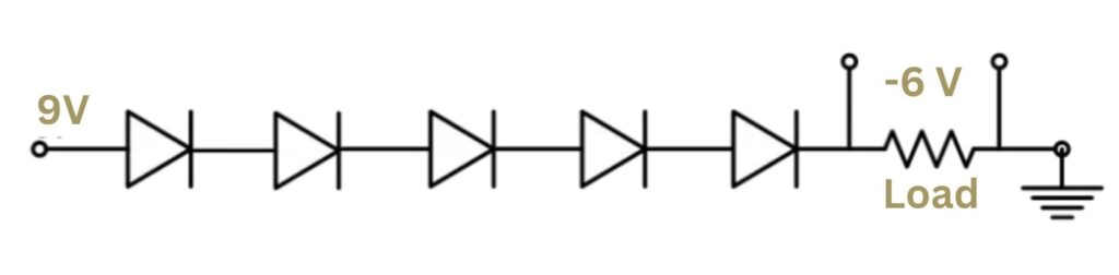
Reduce DC Voltage with Diodes
Let's say we require a 6-volt drop between a 3-volt load and a 9-volt battery. Using silicon diodes with a typical voltage drop of 0.6-0.7 volts each, we can achieve the desired drop by connecting multiple diodes in series. In the illustration, the anode of the first diode connects to the positive terminal of the battery, and subsequently, the anode of the second diode connects to the cathode of the first diode. This series connection cumulatively adds the voltage drops across the diodes, contributing to the overall voltage reduction. For a more precise or significant voltage drop, one can extend this series connection by adding more diodes in a similar manner. This approach allows for flexibility in tailoring the voltage drop according to the specific requirements of the circuit or load.
Recommend: What is a Rectifier Diode: Working and Applications
How to Reduce DC Voltage With Resistors
Reducing DC voltage using resistors involves creating a voltage divider circuit. A voltage divider consists of two resistors connected in series, and the output voltage is taken from the junction between them. The ratio of the two resistors determines the amount of voltage dropped across the circuit. Here's how you can reduce DC voltage using resistors:
Voltage Divider Circuit:
Connect two resistors, R1 and R2, in series.
The voltage across the load (Vout) is taken from the junction between the two resistors.
The voltage drop across the load can be calculated using the voltage divider formula.
Vout = Vin * (R2 / (R1 + R2))
Where:
Vout is the output voltage (voltage across the load),
Vin is the input voltage,
R1 is the resistance of the first resistor,
R2 is the resistance of the second resistor.
Example:
Suppose you have a 12V DC source (Vin) and you want to reduce it to 5V across your load (Vout).
Choose resistor values for R1 and R2. For example, let's use R1 = 10kΩ and R2 = 20kΩ.
Calculate the voltage across the load using the voltage divider formula
Vout = 12V * (20kΩ / (10kΩ + 20kΩ)) = 8V
In this example, the load would experience a voltage drop of 8V, reducing the original 12V input to 8V.
How to Step-up DC Voltage
If you're looking to step-up DC voltage, you've come to the right place. Whether you're a DIY enthusiast or an electronics hobbyist, understanding how to increase the voltage of a direct current (DC) source can come in handy for various projects. In this blog post, we'll explore some methods to step-up DC voltage.
- Voltage Multiplier Circuits: One common method to step-up DC voltage is by using voltage multiplier circuits. These circuits use capacitors and diodes to increase the voltage level. By cascading multiple stages of diodes and capacitors, it's possible to achieve a higher output voltage. Voltage multiplier circuits are commonly used in applications where a high voltage is required, such as in CRT displays or electrostatic precipitators.
- Boost Converters: Another popular method is to use boost converters, also known as step-up converters. These converters use inductors and capacitors to increase the voltage level. By controlling the switching of the components, a boost converter can efficiently step-up the input voltage to a higher output voltage. Boost converters are commonly used in battery-powered devices, such as laptops or smartphones, to provide the necessary voltage for their operation.
- Transformer-based Circuits: Transformers are widely used in electrical systems to step-up or step-down voltage levels. By using a transformer with a higher turns ratio, it's possible to increase the voltage of a DC source. However, it's important to note that transformers work only with alternating current (AC) sources. To step-up DC voltage using a transformer, you'll need to convert the DC source to AC using an inverter, and then use the transformer to step-up the AC voltage. This method is commonly used in high-voltage power transmission systems.
Remember, when working with high voltages, it's crucial to take appropriate safety precautions and follow proper guidelines. Always consult relevant resources and seek expert advice if you're unsure about any aspect of stepping up DC voltage. In conclusion, stepping up DC voltage can be achieved using various methods such as voltage multiplier circuits, boost converters, or transformer-based circuits. Each method has its own advantages and applications, so choose the one that best suits your project requirements. Happy experimenting.
How is DC Voltage Represented on Multimeters?
A multimeter is a tool that helps measure electricity. It can measure things like voltage, current, and resistance. Multimeters come in different sizes and have different features.
To measure voltage, you need to turn the knob on the multimeter to the right range for the voltage you want to measure. Then, you connect the probes (those pointy things) to the right places on the multimeter. Multimeters can measure both types of electricity, AC and DC. If you want to measure DC voltage, make sure the multimeter is set to the DC symbol.
Digital multimeters often have different choices for voltage, like 2V, 20V, 200V, and so on. If you're measuring something below 20V, set the knob to 20V. This makes sure you get the most accurate readings for what you're measuring. It's like choosing the right glasses for your eyes, so you see things clearly.
Conclusion
In conclusion, understanding DC voltage is essential for anyone interested in electronics or electrical circuits. DC voltage, also known as direct current voltage, refers to the constant flow of electric charge in one direction. It is represented by a circuit symbol, which consists of a straight line with a plus sign on one end and a minus sign on the other. DC voltage plays a crucial role in powering various electronic devices and systems. Unlike AC voltage, which alternates its direction periodically, DC voltage remains constant, providing a steady and predictable flow of energy. This characteristic makes it ideal for applications such as batteries, solar panels, and electronic circuits. Furthermore, knowing the circuit symbol for DC voltage enables you to identify and interpret schematics and circuit diagrams. This skill is invaluable when working with electronics, as it allows you to follow instructions, design circuits, and repair devices effectively.
Comment