Introduction
In the world of electrical circuits, the Current Divider Rule is like a fundamental tool for figuring out how electric current is shared in parallel circuits. With technology advancing, there's a growing need to be good at using principles like the Current Divider Rule for designing circuits efficiently. This rule comes into play when you have current flowing through different paths in a circuit, showing you how it gets split among different branches. It's very helpful, especially in dealing with complicated circuits that have things like resistors, capacitors, or other mixed elements. Engineers use it to make sense of currents in intricate setups.
This introduction provides the overview Current Divider Rule, giving us insights into why it matters and where it's useful. Whether you're trying to understand currents in a basic circuit with resistors or dealing with more complex setups involving capacitors and current sources, the Current Divider Rule is a must-know for engineers and students. As we explore its ins and outs, including the formula and how it works in real examples, it becomes clear how important this rule is in analyzing circuits. It's like a key tool in the toolkit of electrical engineers and enthusiasts. When it comes to studying electrical circuits, knowing how current flows and divides is key. The current divider rule is a basic concept that helps engineers and technicians figure out the current in different branches of a parallel circuit. In this article, we'll go through the details of the current divider rule, breaking down its formula and how it all comes together.
What is a Current Divider?
A current divider is a basic electrical circuit that divides an incoming current into two or more branches. It is commonly used in various applications, such as electronics, electrical engineering, and power distribution systems. The concept of a current divider is based on Ohm's Law, which states that the current flowing through a conductor is directly proportional to the voltage across it and inversely proportional to its resistance. In a current divider circuit, the total current entering the circuit is divided among the different branches based on their respective resistances. A current divider is a fundamental circuit concept that allows for the division of an incoming current into multiple branches.
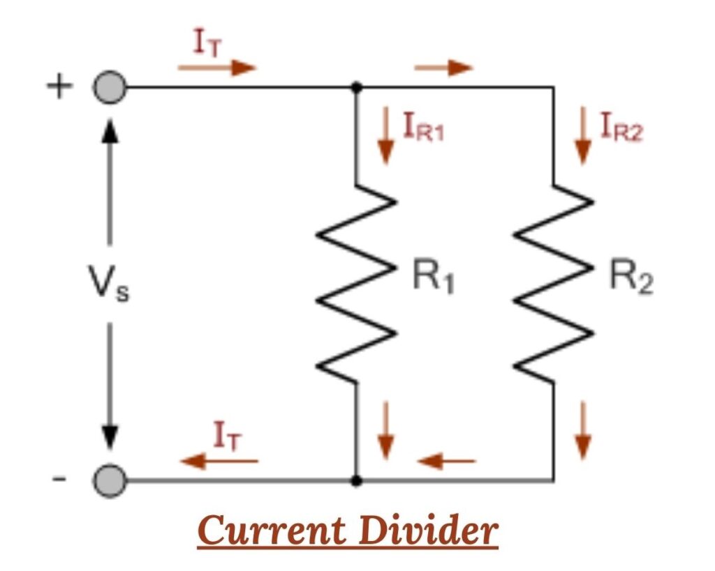
Current dividers refer to parallel circuits where the incoming current from a source is distributed among multiple parallel paths. In such circuits, all components share common terminals, creating separate branches for the current to traverse. Despite varying current values through each component, the voltage across all paths remains constant (VR1 = VR2 = VR3, and so on). This inherent feature of parallel circuits simplifies the determination of branch currents using Kirchhoff's Current Law (KCL) and Ohm's Law, as there is no need to calculate individual resistor voltages.
Recommended: Voltage Dividers: Operations and Functions
In this article, you can explore the definition of voltage dividers, from understanding the basics to their applications. This comprehensive article delves into the voltage divider equation, circuit, and rule, providing clarity on their operations. Learn about Ohm's Law, simplified equations, and the practical applications of voltage dividers in various electronic devices.
Components Free Worldwide Shipping
Current Divider Formula
The current divider formula is a relationship that helps determine the current flowing through each branch of a parallel circuit. In a parallel circuit, the total current (I_total) entering the circuit is divided among the different branches based on their respective resistances.
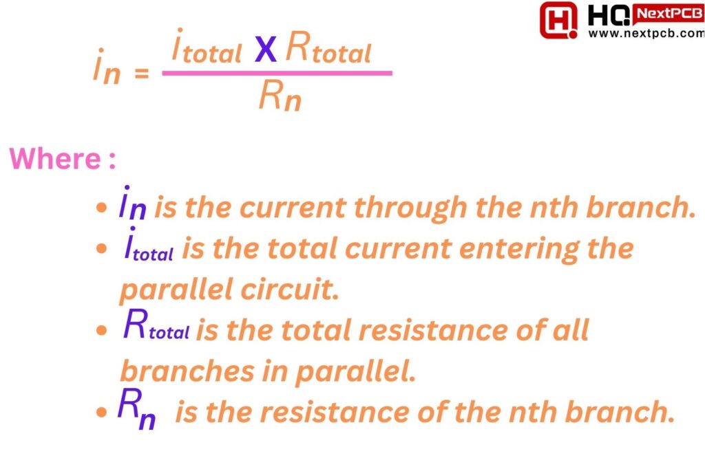
The general formula for calculating the current (I_n) flowing through a specific branch in a parallel circuit is:
Current Divider Formula : I n = (I total X R total ) / Rn
Where :
- I n is the current through the nth branch.
- I total is the total current entering the parallel circuit.
- R total is the total resistance of all branches in parallel.
- R n is the resistance of the nth branch.
Current Divider Formula
Alternatively, you can express the formula in terms of conductance, where conductance (Gn) is the reciprocal of resistance (Gn = 1/ Rn ):
(In = Gn x itotal)
This formula is particularly useful when dealing with parallel circuits, allowing you to determine the current distribution among different paths based on their resistances or conductances.
The current divider formula provides a convenient shortcut for calculating branch currents in a parallel circuit when the total current is known. It establishes that the ratio of the total resistance to the individual resistance equals the ratio of the individual (branch) current to the total current. In simpler terms, this formula allows for a quick and straightforward calculation of the current flowing through a specific branch by considering the relative resistances and currents in the parallel configuration. It proves especially useful when you have the total current information and need to ascertain how that current distributes among the various branches of the circuit without going through extensive calculations.
Current Divider Formula for RC Parallel Circuit
In an RC parallel circuit, the current divider formula can be used to find the current flowing through each branch of the circuit. The current divider formula for a parallel RC circuit is given by:
Ii = I x ( 1 / 1+ jwRiC )
Where:
- Ii is the current flowing through the ith branch (resistor or capacitor).
- I is the total current entering the parallel combination.
- Ri is the resistance of the ith branch.
- C is the capacitance of the capacitor in the ith branch.
- w is the angular frequency of the AC signal (w = 2πf, where f is the frequency).
The formula uses complex impedance for capacitors ( j is the imaginary unit ) because we are dealing with AC circuits. The impedance of a capacitor is
Zc = 1 / jwC
This formula helps you calculate the current in each branch of the parallel RC circuit when you know the total current and the values of resistances and capacitances in each branch. Keep in mind that the current values obtained will be complex numbers, representing both magnitude and phase information.
Current Divider Rule Derivations
When two resistances or impedances are connected in parallel to a power source, the current flowing from the source is split into two separate paths. The magnitude of the current flowing through each path or resistance is determined by the resistance value. Higher resistance results in less current flow, as per Ohm's Law, since the voltage across the parallel combination of resistances remains constant, causing the current to distribute among the individual resistances
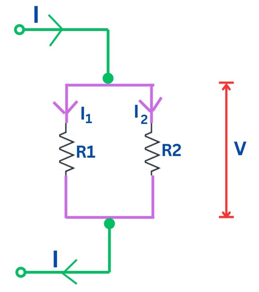
Imagine a circuit with two resistors, R1 and R2, arranged side by side. The current flows through both of them at the same time. We call the current through R1 "I1" and the current through R2 "I2." The voltage drop across both resistors together is called "V." The total current in the circuit is "I." Now, we want to figure out exactly how much current is flowing through R1 (I1) and R2 (I2)
Current Divider Rule Derivations
As the voltage across R1 is V, according to Ohm's Law
I1 = V/R1 …….(3)
Similarly, current through R2 is calculated as below.
I2 = V/R2 …….(4)
Compare the information (3) and (4) with information (1) & (2) respectively. You will notice that the proportionality constant is the voltage V across the combination of resistances. Now, you may find the current I1 & I2 in the same fashion as calculated earlier in the post.
Since, I = I1 + I2
Therefore,
I = V (1/R1 + 1/R2)
So, V = I x [(R1 R2) / (R1+ R2)]
From information (3) and (4),
I1 = Ix[R2/(R1+R2)]
I2 = Ix[R1/(R1+R2)]
Thus, the total current is divided in the inverse ratio of resistance or impedance in parallel connected resistances / impedances. This is the current division rule.
Current Divider Examples
Here are some practical examples of current dividers and how they can be applied in real-world scenarios.
Example-1 : Let's consider a simple lighting circuit with three light bulbs connected in parallel. Each light bulb has a different resistance, and we want to calculate the current flowing through each bulb.
Assuming the total current in the circuit is 2 Amps, and the resistances of the bulbs are 4 ohms, 6 ohms, and 8 ohms respectively, we can use the current divider rule to find the current through each bulb.
Using the formula:
I1 = (R2 * IT) / (R1 + R2 + R3)
where I1 is the current through the first bulb, R1, R2, and R3 are the resistances of the bulbs, and IT is the total current in the circuit.
Plugging in the values, we get:
I1 = (6 * 2) / (4 + 6 + 8) = 0.6 Amps
Similarly, we can calculate the currents through the other two bulbs:
I2 = (4 * 2) / (4 + 6 + 8) = 0.4 Amps
I3 = (8 * 2) / (4 + 6 + 8) = 0.8 Amps
Therefore, the currents through the bulbs are 0.6 Amps, 0.4 Amps, and 0.8 Amps respectively.
Example 2: In some cases, we may have a circuit with multiple loads connected in parallel, and we want to determine the current flowing through each load. Let's consider a scenario where we have three resistors connected in parallel.
Assuming the total current in the circuit is 3 Amps, and the resistances of the resistors are 2 ohms, 4 ohms, and 6 ohms respectively, we can use the current divider rule to find the current through each resistor.
Using the formula mentioned earlier, we can calculate the currents:
I1 = (4 * 3) / (2 + 4 + 6) = 1 Amp
I2 = (2 * 3) / (2 + 4 + 6) = 0.6 Amp
I3 = (6 * 3) / (2 + 4 + 6) = 1.4 Amp
Therefore, the currents through the resistors are 1 Amp, 0.6 Amp, and 1.4 Amp respectively.
Example 3: Current division can also be applied to voltage dividers. Let's consider a voltage divider circuit with two resistors connected in series.
Assuming the total voltage across the circuit is 12 volts, and the resistances of the resistors are 3 ohms and 6 ohms respectively, we can use the current divider rule to find the voltage across each resistor.
Using the formula:
V1 = (R1 * VT) / (R1 + R2)
where V1 is the voltage across the first resistor, R1 and R2 are the resistances, and VT is the total voltage in the circuit.
Plugging in the values, we get:
V1 = (3 * 12) / (3 + 6) = 4 volts
Similarly, we can calculate the voltage across the second resistor:
V2 = (6 * 12) / (3 + 6) = 8 volts
Therefore, the voltage across the resistors is 4 volts and 8 volts respectively.
These examples explain how current division can be used to determine the current or voltage across different components in a circuit. By understanding the current divider rule and applying it correctly, engineers and technicians can design and troubleshoot circuits effectively.
Current Divider for 2 Resistors in Parallel With Current Source
Example : Let's consider an example to illustrate the application of the current divider rule. Suppose we have a circuit with R1 = 2 ohms, R2 = 4 ohms, and a current source supplying 10 amperes. Using the above formulas, we can calculate the currents flowing through each resistor:
I1 = (4 / (2 + 4)) * 10 = 6.67 amperes
I2 = (2 / (2 + 4)) * 10 = 3.33 amperes
Therefore, in this example, R1 will carry approximately 6.67 amperes of current, while R2 will carry approximately 3.33 amperes.
Current Divider for 2 Resistors in Parallel With Voltage Source
Example : Let's say we have a circuit with a voltage source of 12V, and two resistors connected in parallel. R1 has a resistance of 4Ω, and R2 has a resistance of 6Ω. To calculate the current flowing through each resistor, we can use the formula mentioned above:
I1 = (12 / 4) * (6 / (4 + 6))
I2 = (12 / 6) * (4 / (4 + 6))
Simplifying these equations, we get:
I1 = 1.8A
I2 = 0.8A
Therefore, the current flowing through resistor R1 is 1.8A, and the current flowing through resistor R2 is 0.8A.
Current Divider for 3 Resistors in Parallel
Example : Let's illustrate the current divider calculation with an example. Suppose we have a parallel circuit with three resistors: R1 = 10 ohms, R2 = 20 ohms, and R3 = 30 ohms. The voltage across the circuit is 12 volts.
- Calculate the total resistance:
Rt = 1 / (1/10 + 1/20 + 1/30) = 6 ohms
- Calculate the total current:
It = V / Rt = 12 / 6 = 2 amps
- Calculate the current flowing through each resistor:
I1 = It * (1 / R1) = 2 * (1 / 10) = 0.2 amps
I2 = It * (1 / R2) = 2 * (1 / 20) = 0.1 amps
I3 = It * (1 / R3) = 2 * (1 / 30) = 0.067 amps
Therefore, in this example, the current flowing through R1 is 0.2 amps, through R2 is 0.1 amps, and through R3 is 0.067 amps.
When You Can Use the Current Divider Rule
The current divider rule is a useful tool in electrical circuit analysis that allows you to determine the individual currents flowing through different branches of a circuit. It is particularly handy when you have multiple resistors connected in parallel and want to find the current flowing through each resistor.
So, when can you use the current divider rule? Let's take a look at some scenarios where this rule can come in handy:
- Parallel Resistors: The current divider rule is specifically designed for circuits with parallel resistors. When you have two or more resistors connected in parallel, the total current entering the parallel combination splits into individual currents flowing through each resistor. For example, let's say you have two resistors, R1 and R2, connected in parallel. The current divider rule allows you to calculate the current flowing through each resistor based on their respective resistances.
- Equal Voltage Sources : The current divider rule assumes that the voltage sources connected to the parallel resistors are equal. In other words, the voltage across each resistor is the same. If you have different voltage sources, you cannot directly apply the current divider rule. However, you can still use the current divider rule if you can convert the circuit into an equivalent circuit with equal voltage sources. This can be done by using source transformation techniques, such as converting a current source into a voltage source or vice versa.
- Linear Circuit Elements : The current divider rule is applicable to circuits that contain linear elements, such as resistors. Linear elements follow Ohm's law, which states that the current through a resistor is directly proportional to the voltage across it. If your circuit contains non-linear elements, such as diodes or transistors, the current divider rule may not be applicable. In such cases, you will need to use other analysis techniques specific to non-linear circuits.
- Steady-State Conditions : The current divider rule assumes that the circuit is in a steady-state condition. This means that the circuit has reached a stable operating condition where all voltages and currents have settled to their steady-state values. If your circuit is undergoing transient or dynamic behavior, such as during the switching on or off of a circuit element, the current divider rule may not provide accurate results. In these cases, you will need to consider the transient behavior of the circuit using techniques like differential equations or Laplace transforms.
Conclusion
In Conclusion, The current divider rule is a principle used to determine the amount of current flowing through each branch of a parallel circuit. In a parallel circuit, the current splits into multiple paths, and the current divider rule allows us to calculate the current flowing through each branch. The current divider rule is an essential tool for analyzing parallel circuits and determining the current flowing through each branch. By understanding the formula and derivation of the current divider rule, engineers and technicians can accurately calculate currents and design circuits accordingly. Remember to apply this rule whenever you encounter parallel circuits in your electrical projects, as it will greatly simplify the analysis process.
The current divider rule, a valuable tool for analyzing parallel circuits and understanding the distribution of current through different branches, allows you to confidently apply the formula and derivation explained in this article to solve problems related to parallel circuits. Remember to consider the resistance values and the total current flowing through the circuit to calculate the current in a specific branch accurately. Understanding the current divider rule is essential for any electrical engineer or hobbyist working with circuits. It simplifies the analysis of complex circuits and helps in designing efficient electrical systems.
Comment